02 · Initialization and Start-up
rbAmp starts measuring immediately after power-on. The master only needs to:
- Bring up its I2C bus (standard
Wire/ HAL initialization). - Wait ~250 ms, or poll
DATA_VALID = 1at register0xCE. - Optionally read the firmware version from
0x03as a sanity check. - Read data — ready.
No start command, no register-level configuration on the chip is required. Factory calibration is loaded automatically on boot, so the module emits correct physical-unit values from the first reading.

Important for BASIC SCT-series modules used with SCT-013 sensors: after first installation, you must write the sensor model to the model register. The module needs the model to apply the correct mV-per-ampere coefficient. The model code is stored in flash and survives reboots. On firmware before 1.4.20 (
CAPABILITYbit 12 clear) the applied scaling reverts to the factory default after a module restart — a master that selected a non-factory model must re-commit it after every detected module restart (see What persists across a restart and the restart-detection rule in period-metering.md); from fw 1.4.20 the model switch survives a restart. On images before 1.4.20, energy will be wrong after any module restart unlessCT_MODELis re-committed. The client libraries handle both cases for you. Details are in the section Setting the sensor class and CT model below.BASIC CT-series modules are supplied as a pair with their sensors, preset and calibrated for that sensor at the factory; they start without initialization.
In the client libraries — the same task without register access:
Library Call What it does Arduino RbAmp::begin()/RbAmp::waitReady(timeout_ms)probe the module, then wait for the ready flag ESP-IDF rbamp_begin()/rbamp_wait_ready()probe the module, then wait for the ready flag Python dev.begin()/dev.wait_ready(timeout_ms=1000)probe the module, then wait for the ready flag ESPHome rbamp: address:module address set in YAML; the component probes the module at setup
Helper functions (platform-neutral C)
All examples below use three small helpers that are easy to implement on any platform:
// Read one byte from a slave register.
uint8_t rb_read_u8(uint8_t addr, uint8_t reg);
// Read a little-endian float32 (4 bytes from reg, reg+1, reg+2, reg+3).
// rbAmp supports READ auto-increment — both per-byte access and a single
// 4-byte burst-read are valid. The helpers below show per-byte for clarity;
// production code often uses burst-read for atomicity guarantees (see ch 11).
float rb_read_float_le(uint8_t addr, uint8_t reg);
// Write one byte to a slave register.
void rb_write_u8(uint8_t addr, uint8_t reg, uint8_t val);
Bring-up on Arduino (Wire.h)
Helpers
#include <Wire.h>
uint8_t rb_read_u8(uint8_t addr, uint8_t reg) {
  Wire.beginTransmission(addr);
  Wire.write(reg);
  Wire.endTransmission(false);   // repeated start, do not release bus
  Wire.requestFrom(addr, (uint8_t)1);
  return Wire.read();
}
float rb_read_float_le(uint8_t addr, uint8_t reg) {
  uint8_t buf[4];
  for (int i = 0; i < 4; i++) {
    buf[i] = rb_read_u8(addr, reg + i);
  }
  float f;
  memcpy(&f, buf, 4);            // little-endian host (AVR, ESP32, ARM)
  return f;
}
void rb_write_u8(uint8_t addr, uint8_t reg, uint8_t val) {
  Wire.beginTransmission(addr);
  Wire.write(reg);
  Wire.write(val);
  Wire.endTransmission();
}
Smoke test (single module)
#include <Wire.h>
#define RB_ADDR 0x50
void setup() {
  Serial.begin(115200);
  Wire.begin();
  Wire.setClock(50000);
  delay(300);                           // wait for module boot
  // Wait DATA_VALID bit
  while ((rb_read_u8(RB_ADDR, 0xCE) & 0x01) == 0) {
    Serial.println("waiting for DATA_VALID...");
    delay(50);
  }
  uint8_t ver = rb_read_u8(RB_ADDR, 0x03);
  Serial.printf("rbAmp ready, version 0x%02X\n", ver);
}
void loop() {
  float u_rms = rb_read_float_le(RB_ADDR, 0x86);
  float i_rms = rb_read_float_le(RB_ADDR, 0x8E);
  float p     = rb_read_float_le(RB_ADDR, 0xA6);
  float pf    = rb_read_float_le(RB_ADDR, 0xB2);
  Serial.printf("U=%.1f V  I=%.3f A  P=%.1f W  PF=%.3f\n",
                u_rms, i_rms, p, pf);
  delay(1000);
}
Use a load of at least ~1 % of the sensor rating — below that readings get noisy and the class is not given (a 60 W lamp is only 0.9 % of a 30 A clamp; see the characteristics table). On a 30 A clamp, a 2 kW kettle is a good smoke-test load. For BASIC SCT-series modules with an SCT-013 sensor, set the sensor class and CT model before the smoke test (see Setting the sensor class and CT model) — without the model the current readings are meaningless.
Expected output (a 2 kW kettle on 230 V, 30 A clamp):
rbAmp ready, version 0x04
U=229.8 V  I=8.72 A  P=2004 W  PF=0.999
U=230.1 V  I=8.73 A  P=2008 W  PF=0.999
...
Bring-up on STM32 HAL (C)
#include "stm32f1xx_hal.h"
extern I2C_HandleTypeDef hi2c1;
#define RB_ADDR_8BIT (0x50 << 1)        // HAL expects 8-bit address format
uint8_t rb_read_u8(uint8_t reg) {
  uint8_t v;
  HAL_I2C_Mem_Read(&hi2c1, RB_ADDR_8BIT, reg, I2C_MEMADD_SIZE_8BIT, &v, 1, 100);
  return v;
}
float rb_read_float_le(uint8_t reg) {
  uint8_t buf[4];
  for (int i = 0; i < 4; i++) {
    HAL_I2C_Mem_Read(&hi2c1, RB_ADDR_8BIT, reg + i, I2C_MEMADD_SIZE_8BIT,
                     &buf[i], 1, 100);
  }
  float f;
  memcpy(&f, buf, 4);
  return f;
}
void main_app(void) {
  while ((rb_read_u8(0xCE) & 0x01) == 0) HAL_Delay(50);
  uint8_t ver = rb_read_u8(0x03);
  printf("rbAmp version: 0x%02X\n", ver);
  while (1) {
    float u = rb_read_float_le(0x86);
    float i = rb_read_float_le(0x8E);
    float p = rb_read_float_le(0xA6);
    printf("U=%.1f V  I=%.3f A  P=%.1f W\n", u, i, p);
    HAL_Delay(1000);
  }
}
CT-series modules: start-up without configuration
A CT-series module is delivered with every current channel already configured: sensor class, rating and calibration are written at the factory for the clamp packed with that channel. No initialization writes are needed — the host only reads.
⚠ Do not write the sensor class or the sensor model on a CT-series module. - Writing the model to a channel replaces that channel's factory calibration with a generic preset: the current error becomes −2…+3 % and the low-current threshold is wrong. - Writing the class clears the model of every channel.
On firmware 1.4.22 and later a CT-series module refuses class and model writes in normal operation with
ERR_PARAM (0xFE); the client libraries refuse them on all firmware.
The channel and its clamp are a pair. Each clamp is labelled with the channel it belongs to. Do not move a clamp to another channel and do not connect another clamp to a channel: the calibration applies only to the factory pairing. Ratings are fixed; there is no rating to choose.
Start-up sequence
- Connect the clamps (arrow toward the load — see hardware-connection.md) and power the module.
- Read the class (
SENSOR_CLASS,0x25):2= CT clamp series. - Read the applied model of each channel (
0x51..0x53, one register per channel; UI5/UI7 channels 3 and up: through the channel access window, fieldCT_MODEL) and map it to the rating:
| Model code | 0x06 |
0x07 |
0x08 |
0x09 |
0x0A |
0x0B |
0x0D |
|---|---|---|---|---|---|---|---|
| Rating | 1 A | 5 A | 10 A | 20 A | 30 A | 50 A | 100 A |
Use the rating to scale display ranges and to validate readings; the module already reports amperes. 4. Poll as for any BASIC module — measurement window of 100 ms, data-ready pin or periodic read (see realtime-polling.md); period metering as in period-metering.md.
Nothing else is required: there is no sensor selection, no gain step and no save command. The module keeps its configuration across restarts.
Replacing a clamp or a module
The calibration belongs to the pair. A clamp or channel cannot be replaced in the field: a module needing a new clamp is returned to the factory service for re-pairing.
Setting the sensor class and CT model
Required only for BASIC SCT-series modules used with SCT-013 sensors. BASIC CT-series modules are supplied as a pair with their sensors: everything is preset and calibrated at the factory for that particular sensor, and they start without initialization — skip this section.
Two registers describe the external sensor: SENSOR_CLASS (the family — SCT-013 clip-on clamps, the wired CT clamp series, built-in CT) and CT_MODEL (the specific model code within that family). On v1.3 the model is written using a pure-staging scheme — writing CT_MODEL does not apply it on its own; a dedicated per-channel command commits the staged value.
Registers
| Name | Address | Type | Notes |
|---|---|---|---|
SENSOR_CLASS |
0x25 |
u8 RW | 0 = Unset, 1 = SCT_013, 2 = WIRED_CT (the CT clamp series), 3 = BUILTIN_CT (integrated sensor, per-unit factory calibration — no model code). Changing the class resets CT_MODEL to 0. |
CT_MODEL |
0x05 |
u8 RW | CT model code — staging register only. Pure write does not apply. |
Choosing a sensor
Buy one of the voltage-output SCT-013 models listed in the table below (3.5 mm plug) — not a current-output variant. Choose the smallest rated clamp that is above your largest expected current; for the stated class the load should not sit below about 1 % of the rating (see the accuracy table).
CT model codes — SCT-013 family (SENSOR_CLASS = 1)
| Code | Sensor | Rated current | RMS clip onset | Peak limit |
|---|---|---|---|---|
0x00 |
not set (default on factory-fresh BASIC SCT-series modules) | — | — | — |
0x01 |
SCT-013-005 | 5 A | 5.8 A | 8.2 A |
0x02 |
SCT-013-010 | 10 A | 11.6 A | 16.4 A |
0x03 |
SCT-013-030 | 30 A | 34.8 A | 49.2 A |
0x04 |
SCT-013-050 | 50 A | 58 A | 82 A |
0x05 |
SCT-013-100 | 100 A | 116 A | 164 A |
0x06 |
SCT-013-020 | 20 A | 23.2 A | 32.8 A |
0x07 |
SCT-013-060 | 60 A | 69.6 A | 98.4 A |
Codes
0x06and0x07are non-monotonic by rating — they were added after the original0x01..0x05set. Always pick by the rating you need, not by code order.Limit semantics: rated current and RMS clip onset assume a sine-wave load; the measured clip onset is ≈ 1.16 × the rating. The peak limit (≈ 1.64 × rating) is the real ceiling — a distorted load (high crest factor) starts clipping at
peak / crest factor, below the RMS numbers. Stay at or below the rating for specified accuracy: readings clip at about 115–120 % of the rating.
Per-rating figures (detectable and readable floor, class, sensor tolerance, clipping point) are in the accuracy table in overview.md. Changing the sensor model is writing the model code to the module — nothing else is required; there is no recalibration step.
CT model codes — wired CT clamp series (SENSOR_CLASS = 2)
Modules of the CT- series ship as a factory-calibrated set with their own clamp: class and model are already set and are part of the calibration — see CT-series modules: start-up without configuration. Do not write them. The table below is reference for reading the applied model; the user selects nothing on a CT- series module.
| Code | Clamp | Rated current | Window |
|---|---|---|---|
0x01..0x05 |
legacy wired CT presets | — | — |
0x06 |
CT clamp, 1 A | 1 A | 6 mm |
0x07 |
CT clamp, 5 A | 5 A | 6 mm |
0x08 |
CT clamp, 10 A | 10 A | 6 mm |
0x09 |
CT clamp, 20 A | 20 A | 10 mm |
0x0A |
CT clamp, 30 A | 30 A | 10 mm |
0x0B |
CT clamp, 50 A | 50 A | 10 mm |
0x0D |
CT clamp, 100 A | 100 A | 16 mm |
The window size follows from the rated current (6 mm for 1–10 A, 10 mm for 20–50 A, 16 mm for 100 A) and does not affect the calibration.
Commands
| Name | Opcode | Effect | Wait |
|---|---|---|---|
CMD_SET_CT_MODEL_CH0 |
0x28 |
Bind the staged CT_MODEL value to channel 0 |
~5 ms |
CMD_SET_CT_MODEL_CH1 |
0x29 |
Bind to channel 1 (UI2/UI3/I2/I3) | ~5 ms |
CMD_SET_CT_MODEL_CH2 |
0x2A |
Bind to channel 2 (UI3/I3) | ~5 ms |
CMD_SAVE_USER_CONFIG |
0x32 |
Persist user-config block (sensor class, CT model, address, label) to flash | ~700 ms |
Procedure
- Plug the CT clamp(s) into the module's jack(s) (arrow toward the load — see hardware-connection.md).
- Set the sensor class (once, if not already set):
cpp rb_write_u8(0x50, 0x25, 0x01); // SCT_013 - For each channel the module exposes:
- Stage the CT model code to
CT_MODEL:cpp rb_write_u8(0x50, 0x05, 0x03); // example: SCT-013-030- Bind it to the channel with the correspondingCMD_SET_CT_MODEL_CHn:cpp rb_write_u8(0x50, 0x01, 0x28); // CMD_SET_CT_MODEL_CH0 delay(5);- Repeat for ch1 / ch2 if the variant has them (channels are independent — you can mix model codes per channel). - Persist to flash with
CMD_SAVE_USER_CONFIG:cpp rb_write_u8(0x50, 0x01, 0x32); delay(700); // flash erase/write - Done — with one caveat on firmware before 1.4.20 (
CAPABILITYbit 12 clear): there the saved model code survives reboots, but the applied scaling does not (see What persists across a restart below) — if you selected a non-factory model, repeat step 3 (stage + commit) after every detected module restart;CMD_SAVE_USER_CONFIGdoes not need to be repeated. From fw 1.4.20 the model switch survives restarts.
Channel-order independence: on v1.3 you can call
CMD_SET_CT_MODEL_CH0/1/2in any order. There is no descending-order workaround required (that was an internal artifact of earlier firmware).
Behaviour with the current client libraries
The rbAmp client libraries (Arduino, ESP-IDF, ESPHome, Python) wrap this procedure and add:
- Re-writing the same value is skipped. Setting the sensor class or CT model to the value the module already has issues no bus write and no flash cycle — calling the setter on every boot is safe.
- Factory-paired modules refuse class and model changes. On SKUs shipped as a factory-calibrated
set with their own current sensor (the CT- series), the sensor class and model are part of the
calibration: the module (firmware 1.4.22 and later) refuses the write with
ERR_PARAM (0xFE)in normal operation, and the libraries refuse it before sending on all firmware. Re-pairing a replacement sensor is a factory service. - Per-model limits. For each CT model the libraries expose its nominal current, the RMS level where clipping sets in, and the peak limit — use them to validate readings against the connected sensor.
Verification
After binding, the applied CT model on each channel is mirrored at 0x51..0x53 (read-only verify mirrors). These are NOT the staging register 0x05:
uint8_t ch0 = rb_read_u8(0x50, 0x51);  // applied on ch0
uint8_t ch1 = rb_read_u8(0x50, 0x52);  // applied on ch1
uint8_t ch2 = rb_read_u8(0x50, 0x53);  // applied on ch2
Serial.printf("Applied: ch0=0x%02X ch1=0x%02X ch2=0x%02X\n", ch0, ch1, ch2);
⚠ Readback ≠ persistence. A successful read of
0x51..0x53confirms the value is live in RAM, not that it survived to flash. To verify persistence, issueCMD_RESET(or power-cycle) and re-read after the boot window. The full pattern is in period-metering.md.When commissioning a new module, perform a sanity check with a known resistive load (for example a 100 W incandescent lamp):
I_rms ≈ 100 W / U_rms ≈ 0.43 AandP_real ≈ 100 W. If readings are off by a large factor, the model code is probably wrong.
What persists across a restart
CMD_SAVE_USER_CONFIG persists the user-config block to flash, but not everything a master sets is
re-applied on the next boot. On firmware before 1.4.20 (CAPABILITY bit 12 clear):
| Item | Survives a restart? |
|---|---|
| I²C address | yes |
| Module label | yes |
| Sensor class + CT model code (readable back) | yes |
| Applied per-model scaling | before fw 1.4.20: no — reverts to the factory default; from 1.4.20 (CAPABILITY bit 12 set): yes |
FLEET_CONFIG (GC enable) + GROUP_ID |
yes (via CMD_SAVE_USER_CONFIG; effective after reset) |
| RAM-only config (event thresholds, digest config) | no |
The consequence on those images: a module that was switched to a different model than it left the factory with reads back the saved model code after a restart, yet measures with the factory scaling until the model is committed again. The rule for any master (and for a hub managing a fleet, keyed by module UID):
- Detect the restart —
UPTIME_S/RESET_OCCURREDevent bit, see period-metering.md → Detecting a module restart. - Re-stage and re-commit the CT model on every channel (
CT_MODEL+CMD_SET_CT_MODEL_CHn), then re-apply any RAM-only configuration.
The client libraries implement exactly this in their resume path. From fw 1.4.20 (CAPABILITY
bit 12, SCT_RATING_SELF) the model switch keeps the unit calibration and survives restarts —
step 2 is then unnecessary for the CT model; RAM-only configuration still needs re-initialising.
Modules running on their factory model (including every factory-paired CT- series module) are
unaffected on every image — the factory scaling is the correct one.
In the client libraries — the same task without register access:
Library Call What it does Arduino RbAmp::setSensorClass(cls)/RbAmp::setCTModel(channel, code)set the sensor class and the per-channel CT model ESP-IDF rbamp_set_sensor_class()/rbamp_set_ct_model_ch()set the sensor class and the per-channel CT model Python dev.set_sensor_class(cls)/dev.set_ct_model_ch(channel, code)set the sensor class and the per-channel CT model ESPHome sensor_class:/ct_model:YAML options for the sensor class and CT model
Single-module workflow
- Wire the module according to hardware-connection.md.
- For BASIC SCT-series modules, write the sensor model once (previous section).
- Flash the master with the smoke-test sketch.
- Open the serial monitor — you should see U/I/P every second.
- If readings look wrong, see troubleshooting.md.
Multi-module setup
Scenario: three rbAmp modules on a single bus to monitor different sections of a house (main feed, water heater, air conditioner).
Step 1 — Addresses
Out of the box all three modules carry address 0x50. They must be readdressed one at a time. Connect only one module to the bus until readdressing is complete.
Step 2 — Smoke test with one module
Use the section above. Confirm one module works correctly.
Step 3 — Readdress (and, if needed, set the CT model)
Use the address-change procedure below. If the modules use different SCT-013 sensors, set the CT model on each one before readdressing.
Step 4 — Multi-module polling loop
#include <Wire.h>
const uint8_t modules[] = {0x50, 0x51, 0x52};   // main, boiler, AC
const char* labels[]    = {"MAIN", "BOIL", "AC  "};
const int N = sizeof(modules) / sizeof(modules[0]);
void setup() {
  Serial.begin(115200);
  Wire.begin();
  Wire.setClock(50000);
  delay(300);
  for (int i = 0; i < N; i++) {
    Wire.beginTransmission(modules[i]);
    uint8_t rc = Wire.endTransmission();
    Serial.printf("Module %s (0x%02X): %s\n",
                  labels[i], modules[i], rc == 0 ? "OK" : "MISSING");
  }
}
void loop() {
  for (int i = 0; i < N; i++) {
    float u = rb_read_float_le(modules[i], 0x86);
    float p = rb_read_float_le(modules[i], 0xA6);
    Serial.printf("[%s] U=%.1f  P=%.1f W\n", labels[i], u, p);
  }
  Serial.println();
  delay(1000);
}
Expected output:
Module MAIN (0x50): OK
Module BOIL (0x51): OK
Module AC   (0x52): OK
[MAIN] U=229.8  P=850.3 W
[BOIL] U=229.7  P=1850.0 W
[AC  ] U=229.9  P=0.0 W
...
In the client libraries — the same task without register access:
Library Call What it does Arduino RbAmpFleet::scan(match_product, added)/RbAmpFleet::pollAll(snaps, status, capacity, n_ok)discover the modules on the bus; read all of them in one pass ESP-IDF rbamp_fleet_scan()/rbamp_fleet_poll_all()discover the modules on the bus; read all of them in one pass Python fleet.scan(match_product=True)/fleet.poll_all()discover the modules on the bus; read all of them in one pass ESPHome rbamp: (list)one rbamp:block per module, each with its ownidandaddress
Address change
The factory address 0x50 is stored in the user-config block in flash. v1.3 uses a two-phase commit sequence to make accidental address changes hard: a candidate address goes into a RAM staging register first, has to be armed with a magic byte, and only then is committed to flash by an explicit command. A reset re-enumerates the module at the new address.
Registers and commands
| Name | Address / opcode | Type | Purpose |
|---|---|---|---|
REG_I2C_ADDRESS |
0x30 |
u8 RW | Staging for the candidate address (0x08..0x77). One rule: before the reset, 0x30 echoes the staged candidate; after boot it reads the active address. |
ADDR_COMMIT_MAGIC |
0x31 |
u8 W | Arm the commit with 0xA5. Consumed (cleared) on the commit attempt. |
CMD_COMMIT_ADDR |
opcode 0x30 written to REG_COMMAND (0x01) |
command | Validates the staged address against the magic, persists to flash. |
CMD_RESET |
opcode 0x01 written to REG_COMMAND (0x01) |
command | Soft reset. Module re-enumerates at the new address after ~300 ms. |
Procedure
- Connect only one module (still on
0x50) to the bus. - Stage the new address:
cpp rb_write_u8(0x50, 0x30, 0x51); // candidate address → RAM staging - Arm the commit:
cpp rb_write_u8(0x50, 0x31, 0xA5); // ADDR_COMMIT_MAGIC - Issue
CMD_COMMIT_ADDR(opcode0x30):cpp rb_write_u8(0x50, 0x01, 0x30); - Wait ≥ 700 ms for the flash erase/write:
cpp delay(700); - Issue
CMD_RESET(opcode0x01) —CMD_COMMIT_ADDRdoes not auto-reset:cpp rb_write_u8(0x50, 0x01, 0x01); - Wait ~300 ms for the boot window. Do not issue commands during this window.
- Verify the module ACKs at the new address:
cpp uint8_t ver = rb_read_u8(0x51, 0x03); // VERSION should be 0x04 on v1.3 if (ver == 0x04) Serial.println("Address change OK"); - Mark the PCB with the new address using a wax pencil or label so you can identify the module physically.
Important notes
- Both stages are mandatory. Writing the candidate to
0x30alone does nothing persistent — it only lands in RAM and is lost on the next reset. The magic-and-commit pair is what actually rewrites flash. - The staged address must lie in the range
0x08..0x77(valid 7-bit I²C). Out-of-range writes are rejected withERR_PARAM; the module keeps its current address. - Reserved I²C addresses:
0x00(general-call, see below),0x01..0x07(CBus reserved),0x78..0x7F(10-bit reserved). Do not use these. - One read-back rule: before the reset
0x30echoes the staged candidate; after boot it reads the active address. - The armed magic expires after 5 s without a commit (chapter 11 §6.1) — re-arm if you waited too long.
- Namespace reminder — the same byte value can be an address and an opcode:
| Byte | As a register address | As an opcode (written to 0x01) |
|---|---|---|
0x27 |
FLEET_CONFIG |
CMD_LATCH_PERIOD |
0x28 |
GROUP_ID |
CMD_SET_CT_MODEL_CH0 |
0x30 |
REG_I2C_ADDRESS |
CMD_COMMIT_ADDR |
Full address-change example
#include <Wire.h>
bool change_address(uint8_t old_addr, uint8_t new_addr) {
  if (new_addr < 0x08 || new_addr > 0x77) {
    Serial.println("ERROR: invalid address");
    return false;
  }
  Serial.printf("Changing 0x%02X -> 0x%02X\n", old_addr, new_addr);
  rb_write_u8(old_addr, 0x30, new_addr);   // 1. stage candidate
  rb_write_u8(old_addr, 0x31, 0xA5);       // 2. arm magic
  rb_write_u8(old_addr, 0x01, 0x30);       // 3. CMD_COMMIT_ADDR
  delay(700);                              // 4. flash erase/write
  rb_write_u8(old_addr, 0x01, 0x01);       // 5. CMD_RESET (mandatory)
  delay(300);                              // 6. boot window
  Wire.beginTransmission(new_addr);
  if (Wire.endTransmission() == 0) {
    Serial.printf("OK, module now at 0x%02X\n", new_addr);
    return true;
  }
  Serial.printf("FAIL: module not found at 0x%02X\n", new_addr);
  return false;
}
void setup() {
  Serial.begin(115200);
  Wire.begin();
  delay(300);
  change_address(0x50, 0x51);
}
In the client libraries — the same task without register access:
Library Call What it does Arduino RbAmp::prepareAddressChange(new_addr)/RbAmp::commitAddressChange()stage and arm the new address, then commit it ESP-IDF rbamp_prepare_address_change()/rbamp_commit_address_change()stage and arm the new address, then commit it Python dev.prepare_address_change(new_addr)/dev.commit_address_change()stage and arm the new address, then commit it ESPHome new_address:one-time address change at boot; remove the option afterwards
General Call (broadcast at address 0x00)
The I²C protocol reserves address 0x00 (general call) — frames sent to this address are received by all slaves on the bus simultaneously. rbAmp can take its period snapshot on a general-call frame, but only after the feature has been explicitly enabled on the module.
Opt-in enable (default OFF)
GC snapshot reception is disabled by default — a fresh module will NACK the general-call frame, which the master detects as a hard error and falls back to per-module sequential snapshot automatically. To enable GC on a module:
- Set bit 0 of
FLEET_CONFIG:cpp rb_write_u8(0x50, 0x27, 0x01); // bit0 = GC_ENABLE
Note on the value
0x27: this is the register address ofFLEET_CONFIG. The same byte value0x27also happens to be the command opcode forCMD_LATCH_PERIOD(a separate namespace — opcodes go intoREG_COMMANDat0x01). The collision is purely cosmetic; the address and opcode are never confused at the wire level. 2. (Optional) setGROUP_IDfor fleet partitioning —0x00accepts all-call:cpp rb_write_u8(0x50, 0x28, 0x00); // all-call3. Persist:cpp rb_write_u8(0x50, 0x01, 0x32); // CMD_SAVE_USER_CONFIG delay(700);4. Reset and verify the bit landed:cpp rb_write_u8(0x50, 0x01, 0x01); // CMD_RESET delay(300); uint8_t cfg = rb_read_u8(0x50, 0x27); if (cfg & 0x01) Serial.println("GC enabled");
GC frame format
GC snapshot frames have a fixed magic-and-opcode layout:
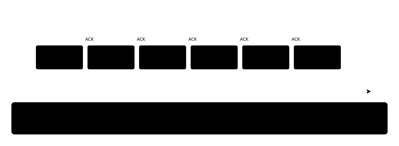
addr 0x00 | A5 27 <group_id> <tick_lo> <tick_hi>A5— frame magic (the slave rejects any other byte).27— opcode (CMD_LATCH_PERIOD).<group_id>— target group (0x00= all-call; otherwise must match the module'sGROUP_ID).<tick_lo/hi>— master-side 16-bit tick counter, mirrored into each module'sGC_TICK (0x59)register for missed-frame detection.
By design GC frames carry only the snapshot command — destructive opcodes (SAVE_*, COMMIT_ADDR, FACTORY_RESET) are not honoured over general-call.
Broadcast snapshot example (after enable)
// All modules with GC enabled take their snapshots at once.
Wire.beginTransmission(0x00);
Wire.write(0xA5);                       // frame magic
Wire.write(0x27);                       // CMD_LATCH_PERIOD opcode
Wire.write(0x00);                       // group_id = all-call
Wire.write(tick & 0xFF);                // tick_lo
Wire.write((tick >> 8) & 0xFF);         // tick_hi
uint8_t rc = Wire.endTransmission();
if (rc != 0) {
  // NACK at GC level → no module on the bus has GC enabled.
  // Fall back to per-module sequential snapshot.
}
After the broadcast, each module updates its snapshot independently. The master then reads each module by its individual address. Witness check (recommended): after ~50 ms settle, read V03_PERIOD_VALID (0x07) on each expected module — 1 confirms the snapshot landed; 0 falls back to per-module snapshot on that module only.
Application: precise period synchronisation for multi-module energy balancing (e.g. mains_input − solar_output), where the snapshot instant must be identical across modules.
In the client libraries — the same task without register access:
Library Call What it does Arduino RbAmp::enableGc(enable)/RbAmpFleet::gcLatch(group, tick, settle_ms)enable General Call on a module; send the snapshot frame to the fleet ESP-IDF rbamp_enable_gc()/rbamp_fleet_gclatch()enable General Call on a module; send the snapshot frame to the fleet Python dev.enable_gc(enable=True)/fleet.gc_latch(group, tick, settle_ms)enable General Call on a module; send the snapshot frame to the fleet ESPHome fleet_gc_enable:/group_id:YAML options for General Call opt-in and group id
Recommended multi-module deployment workflow
Step 1: Unbox all modules — every module is on address 0x50.
Step 2: For each module, one at a time:
   a) Connect only this module to the bus.
   b) If it is a BASIC SCT-series module: set SENSOR_CLASS (0x25), stage CT_MODEL (0x05),
      issue CMD_SET_CT_MODEL_CHn for each channel, then CMD_SAVE_USER_CONFIG.
   c) On images before fw 1.4.20 (`CAPABILITY` bit 12 clear): after any later reset of this
      module, re-stage and re-commit CT_MODEL on each channel (see the persistence table above).
   d) Run change_address(0x50, <new_address>).
   e) Verify the module responds at the new address.
   f) Physically mark the module (label with 0x51, 0x52, ...).
   g) Disconnect and move to the next module.
Step 3: After readdressing all modules, connect them in parallel.
        With four or more modules (or a longer bus), cut the built-in
        pull-up jumpers on all but one (see hardware-connection.md → I2C pull-ups).
Step 4: At master boot, run a scan loop and verify every readdressed
        module responds at its expected address.
BASIC or STD?
The rbAmp STD line answers on the same bus but uses a different, 16-bit register map. Before
applying the BASIC detection below, you can discriminate: send the 16-bit pointer 0x00 0x00 and
read 2 bytes — an STD module returns the ASCII pair 'S','T' (0x53 0x54); a BASIC module does not
(it treats the bytes as 8-bit register writes and returns its normal data). STD modules are covered
by their own reference documentation.
You do not need to do this yourself when you use a client library. The libraries (Arduino, ESP-IDF, Python, ESPHome) already detect the module line and handle the different register sizes — you do not have to think about whether the register map is 8-bit or 16-bit.

In the client libraries — the same task without register access:
Library Call What it does Arduino RbAmp::line()/RbAmp::begin()line detected in begin(); read it back from the cached value ESP-IDF rbamp_line()/rbamp_begin()line detected in begin; read it back from the cached value Python dev.is_std/dev.begin()line detected in begin(); read it back from the property ESPHome — not exposed — detection is automatic, nothing to configure in YAML
Module variant auto-detection
⚠ Do not detect the variant by probing for a NACK on register reads. The firmware never NACKs on register reads — unmapped addresses return
0x00(see chapter 11 §5.2). A NACK-based check always reports "channel present".
Use the canonical pair HW_VARIANT (0x55) + CAPABILITY (0x57/0x58):
struct VariantInfo {
  uint8_t hw_variant;     // 1=UI1, 2=UI2, 3=UI3, 4=I1, 5=I2, 6=I3
  uint8_t n_current;      // 1..3
  bool    has_voltage;    // true on UI*, false on I*
};
VariantInfo detect_variant(uint8_t addr) {
  VariantInfo v = {0, 0, false};
  uint8_t product = rb_read_u8(addr, 0x54);             // PRODUCT_ID
  if (product != 0x01) return v;                         // not an rbAmp sensor
  v.hw_variant = rb_read_u8(addr, 0x55);                 // HW_VARIANT
  uint8_t hw = v.hw_variant;
  v.n_current = (hw == 1 || hw == 4) ? 1
              : (hw == 2 || hw == 5) ? 2
              : (hw == 3 || hw == 6) ? 3 : 0;
  uint8_t cap_hi = rb_read_u8(addr, 0x58);               // CAPABILITY high byte
  v.has_voltage = (cap_hi & 0x01) != 0;                  // bit 8 of u16 = voltage-HW
  return v;
}
HW_VARIANT 1..3 are UI-variants (has_voltage == true); 4..6 are I-only variants (has_voltage == false). Mismatch between HW_VARIANT family and CAPABILITY.bit8 indicates a broken / mis-flashed module.
AC_FREQ (0x20) works on all variants — the zero-cross signal comes from a dedicated mains-ZC pin independent of the voltage front-end.
In the client libraries — the same task without register access:
Library Call What it does Arduino RbAmp::readVariant()/RbAmp::readCapability(out)read the hardware variant and the capability map ESP-IDF rbamp_read_variant()/rbamp_read_capability()read the hardware variant and the capability map Python dev.read_variant()/dev.read_capability()read the hardware variant and the capability map ESPHome get_variant_str()/get_capability_hex()variant string and capability bitmap from the identity surface
Next
- realtime-polling.md — real-time polling in depth (100 ms window, DRDY)
- period-metering.md — tariff energy accumulation