Measure & Meter · rbAmp Standard (STD) · available
Import and export counted separately — and kept when your controller reboots
With solar on the roof, one total on the meter mixes what you bought with what you sold, and a counter kept in your controller starts over when it reboots. An STD meter counts import and export on the device itself and keeps the records, while the meter is powered — when the controller reboots, updates or disconnects.
Metering starts by itself at power-up; your controller sets the time and reads the data. Single-phase STD-UI1 and three-phase STD-U3I3, each with calibrated sensors in the kit; I²C or Modbus RTU for your own monitoring system.
The meter keeps counting. Your controller doesn't have to.
The meter measures, integrates energy and keeps separate import and export counters — on its own, saved every second. Your controller reads the accumulated values whenever it is there. When it reboots, updates or loses the link, the counters on the meter lose nothing: read them again when it is back. A power cut under load loses about a second of energy at most.
Autonomy of metering is not autonomy of power: the meter must stay powered to keep counting.
Source: Docs › STD › Energy and periods
STD meterillustrative, not a live reading
Metering active
IMPORT
1,284.52 kWh
EXPORT
426.18 kWh
Energy saved on the meter: every second
Controller: offline — ESP32 / Raspberry Pi / PLC
Read the counters when the controller reconnects
Choose your meter
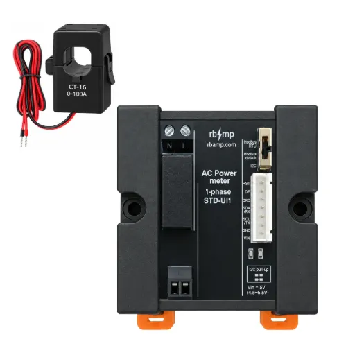
STD-UI1 — single-phase energy meter
For a single-phase input, a solar installation, a single machine, a small site. 1 voltage + 1 current channel · import and export counters on the meter · sensor 60 A or 100 A in the kit, calibrated with its channel · I²C or Modbus RTU. STD-UI1 in the docs
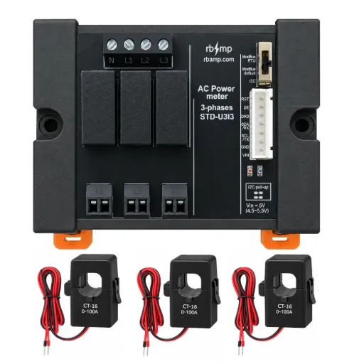
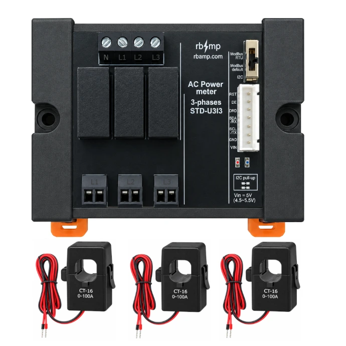
STD-U3I3 — three-phase energy meter
For a three-phase input, a workshop or production floor, a charging site, a three-phase solar system. 3 voltage + 3 current channels, sampled synchronously · import and export by the phase balance · phase-sequence check · three kit sensors, 60 A or 100 A, labelled per channel · I²C or Modbus RTU. Neutral required — voltage terminal N, L1, L2, L3. STD-U3I3 in the docs
Which rating? Pick the smallest kit rating above the circuit's maximum current: a 40 A main → 60 A; a 63 A main → 100 A. The sensors are calibrated with their channels — keep each sensor on the channel it is labelled for.
Import and export are counted separately
A single net figure cannot tell you how much came from the grid and how much went to it. STD keeps two independent counters for active energy — import and export — and two for reactive. They only grow, so import and export never cancel each other. Interval energy is the difference of two readings; a missed boundary merges two intervals and loses nothing.
STD-U3I3: the direction follows the balance of the three phases — the standard meter convention: a site exporting on one phase while importing on another is counted correctly.
Grid connectionillustrative, not a live reading
Grid import
1,284.52 kWh
Energy taken from the grid
Grid export
426.18 kWh
Energy delivered to the grid
More than a counter: a record of your energy
Lifetime counters
Import and export, active and reactive; they never go down; journaled storage falls back to the last good copy.
Hourly history
The last 7 hourly records (energy and an electrical summary for each hour) survive a restart.
Snapshot banks
Eight independent banks: each consumer cuts its own period (a minute, 15 minutes, an hour) without disturbing the others.
Event log
Counter resets and adoptions, calibration saves and firmware updates, with before and after values.
- On the meter: the counters, the last hours, the snapshots and the log — the source of truth.
- On your master: the long archive, trends, tariffs and analytics — in rbgrid, Home Assistant or your own code.
The meter has no battery clock: your master sets the time after each restart. Counters run without it; hourly records are written once the time is set.
Source: Docs › STD › Energy and periods
High-resolution measurement, down to very small loads
Resolution
Current is published in microamperes and energy is counted in microwatt-hours. This is the step of the numbers, not an accuracy claim.
Start threshold
Below a starting current (400 µA by default, configurable) a channel adds no energy, so an idle circuit does not creep. Readings are not affected.
What this means: a standby load that a coarse reading would bury in noise shows as a steady value — small currents are smoothed over a few seconds for a stable reading — and the start threshold keeps the counter still at zero.
Measured characteristics — STD-UI1
Measured on one production module per kit (60 A and 100 A), each channel individually calibrated together with its sensor, against a reference meter on a resistive load. Current is given as the primary current with one pass of the wire through the sensor; on STD-U3I3 the figures cover all three channels.
| Parameter | 60 A kit | 100 A kit |
|---|---|---|
| Class | ±0.2 % in range 0.005 A – 75 A | ±0.2 % in range 0.005 A – 100 A |
| Upper end of the range | 75 A | 129 A |
| Voltage error | ±0.2 % | ±0.2 % |
| Power factor, resistive load | 0.999–1.000 | 0.999–1.000 |
| Reads from | 4.8 mA | 4.8 mA |
| Noise with no current | 0.2 mA | 0.35 mA |
Measured characteristics — STD-U3I3
Measured on one production module per kit (60 A and 100 A), each channel individually calibrated together with its sensor, against a reference meter on a resistive load. Current is given as the primary current with one pass of the wire through the sensor; on STD-U3I3 the figures cover all three channels.
| Parameter | 60 A kit | 100 A kit |
|---|---|---|
| Current error | ±0.2 % in range 0.005 A – 75 A | ±0.2 % in range 0.005 A – 100 A |
| Upper end of the range | 75 A | 129 A |
| Voltage error | ±0.2 % | ±0.2 % |
| Power factor, resistive load | 0.999–1.000 | 0.999–1.000 |
| Reads from | 4.8 mA | 4.8 mA |
| Noise with no current | 0.2 mA | 0.35 mA |
One meter, two integration paths
I²C: for ESP32, Arduino, Raspberry Pi and your own electronics
The full register map, the same client libraries as BASIC (the library detects the module at start), a data-ready output, one bus for STD and BASIC together — change the default address of one of them first.
Modbus RTU: for inverters, PLCs, SCADA and your own Modbus master
The module has no RS-485 transceiver: the connector carries UART TTL and a driver-enable line for an external transceiver. The meter answers as a standalone Modbus device: a native integer map; a float32 register profile of 13 values (points outside the list read 0; register map in the STD docs); per-channel virtual unit ids on STD-U3I3. Switch position «Modbus default»: 9600 8N1, unit 1. Frames 8N1 / 8E1 / 8O1 / 8N2, from 2400 baud.
The interface is chosen with a three-position switch — Modbus RTU · Modbus default · I²C — read at power-up; move it and restart to change. Modbus needs no library: any Modbus master reads the meter.
Source: Docs › STD › Hardware · Reference › Modbus
See all three phases at once
STD-U3I3 is not three single-phase meters on one board. All six channels are sampled synchronously in one measurement window: per-phase voltage, current, power and power factor come from the same instant, and the totals are built from them. Energy direction follows the phase balance.
Before you trust per-phase readings, the meter reports the phase angles and whether the sequence is forward, reverse or abnormal — a wiring check built in.
Source: Docs › STD › STD-U3I3
STD-U3I3illustrative, not a live reading
| L1 | 230.4 V | 8.42 A | 1.82 kW |
|---|---|---|---|
| L2 | 229.8 V | 5.16 A | 1.08 kW |
| L3 | 231.1 V | 3.70 A | 0.76 kW |
| Total | 3.66 kW |
Designed for continuous operation
Device identity and signed measurement records
Each meter carries a unique device certificate and answers a challenge from your master. Energy and log records are signed by the device, so records copied from another device or edited outside it are detected.
Counters that survive
Saved every second, journaled, restored from the last good copy. If the storage becomes unavailable the meter keeps metering and recovers when it returns.
Service
Status LEDs show metering and faults; an IDENTIFY command blinks them to find the meter in a cabinet.
Designed for electrical panel installation
STD-UI1 and STD-U3I3 are galvanically isolated: the connector side (VIN, GND, bus) is isolated from the mains measurement inputs. The board comes in an enclosure that covers the lower part with all mains circuits; the upper part with the interface connector is open and isolated; only the voltage-sensor terminal comes out, in a plastic housing. The enclosure has a DIN clip and can be installed in a cabinet.
- one 7-pin interface connector: power, ground, bus, data-ready, driver enable, reset
- voltage input: a thin wire is enough (AWG26–22); a fuse in the L line is mandatory, rated up to 0.1 A
- STD-U3I3: voltage terminal N, L1, L2, L3 — neutral required; fuse each L line
- sensors: the kit comes pre-connected; each sensor stays on the channel it is labelled for; follow the arrow for the import direction
Safety. The measurement inputs connect to mains. For work inside an electrical panel, call a qualified electrician.
STD is a sub-metering and monitoring instrument. It is not a utility settlement meter and makes no certification claims.
Source: Docs › STD › Hardware
From power-on to energy metering
1 · Fit the sensors.
Clamp each sensor on its conductor, arrow toward the load; keep it on the channel it is labelled for. No sensor calibration required.
2 · Set the switch, connect and power.
Choose I²C or Modbus on the interface switch, connect the bus and power the meter. Metering starts by itself.
3 · Set the time from your controller.
Once after each power-up — there is no battery clock. Counters run even without it.
4 · Read the data.
Live values about ten times a second, the counters, the records and the events.
Metering runs independently. After this your controller can go away and come back; the meter keeps counting while it is powered.
Source: Docs › STD › Quick start
What you can build
Home with solar
Import and export as two counters in your dashboard. STD-UI1 on the input · I²C → ESP32.
Meter for an inverter or SCADA
The meter your Modbus master reads. STD over Modbus RTU with an external transceiver · Modbus.
Three-phase workshop or building
Per-phase readings and totals. STD-U3I3 on the input · I²C or Modbus.
EV charging site
Energy per charger. STD-U3I3 per charger · I²C or Modbus. Not a protective device.
Tenants on one meter
Energy per current channel from the meter's own map; on Modbus each channel can also answer as its own single-phase view (voltage, current, power). STD-U3I3 · I²C or Modbus.
Home Assistant node
Counters and live values in Home Assistant. STD + ESP32 · ESPHome.
BASIC + STD: one installation, many measurement roles
STD takes the points where the numbers must be right — the grid input, the inverter, the charger. BASIC adds the branches — boiler, heat pump, lighting, workshop. One bus, one library, one controller: STD is the source of truth, BASIC fills in the picture. Start with one STD; add BASIC when you want the branches.
Main grid input — STD → branches — BASIC → ESP32 / Raspberry Pi / PLC
Technical specifications
Every line below is available.
| Measurement | synchronous sampling, about 3 kHz per channel · windows of whole mains cycles, a complete snapshot about ten times a second · per channel: RMS voltage and current, active power (signed), reactive and apparent power, power factor (signed), frequency · phase angles and phase sequence (STD-U3I3) · current in µA, energy in µWh · start threshold 400 µA by default, configurable |
|---|---|
| Energy and records | import and export, active and reactive · lifetime counters, journaled, saved every second · hourly history, last 7 records, survives a restart · eight snapshot banks · event log with before/after values · time set by the master (no battery clock) |
| Interfaces | I²C, 16-bit register map, address 0x50 by default · Modbus RTU from 2400 baud, 8N1 / 8E1 / 8O1 / 8N2, configurable word order · native register map · float32 register profile of 13 values · virtual unit ids (STD-U3I3) · discovery block · validated settings writes; reset, calibration and update need an explicit unlock · three-position interface switch, read at power-up · data-ready output · external RS-485 transceiver required (UART TTL + driver enable on the connector) |
| Update and identity | two firmware copies · signed and encrypted image · automatic rollback · older images refused · update over the working bus while metering continues · device certificate · signed records |
| Hardware | 7-pin connector · VIN 4.5–5.5 V, 30 mA typical, 50 mA max · 3.3 V logic · I²C pull-up jumpers on the board · two status LEDs, IDENTIFY · enclosure with DIN clip · voltage input fuse up to 0.1 A in each L line |
| Kit | current sensor per channel, 60 A or 100 A, calibrated with its channel and labelled |
| Measured characteristics | STD-UI1 and STD-U3I3 — above |
The STD family
One contract, one library: the channel count is discovered at run time.
Libraries and documentation
Arduino · ESP-IDF · Python · ESPHome / Home Assistant — STD support: in validation until release. Modbus needs no library: any Modbus master reads the meter.
Questions
Can STD be a utility settlement meter?
No. It is a sub-metering and monitoring instrument and makes no certification claims; it is not for utility settlement.
Does it need a controller?
Only to set the time and read the data. Metering starts by itself at power-up and keeps running while the meter is powered.
Do I need an RS-485 adapter?
For a Modbus network, yes: the meter carries UART TTL and a driver-enable line for an external transceiver.
What happens on power loss?
Energy is saved every second; a power cut under load loses about a second of energy at most. The counters continue from the last saved value.
Why set the time?
The meter has no battery clock. Counters run without it; hourly records need it.
Can I mix STD with BASIC?
Yes, on one I²C bus with one library. Both answer at the same default address, so change the address of one of them before connecting both.
Can I switch between I²C and Modbus later?
Yes. Move the interface switch and restart the meter; the switch is read at power-up.
60 A or 100 A?
The smallest rating above the circuit's maximum current. The sensors stay on the channels they are labelled for.
Is it accurate to a microampere?
No. A microampere is the resolution — the smallest step of the numbers, not the accuracy. Current is read from about 5 mA. On production modules the measured current error is within ±0.2 % from 5 mA to 75 A with the 60 A kit and to 100 A with the 100 A kit. Full figures for the 60 A and 100 A kits: Measured characteristics and the docs.