03 · Current Sensor Selection
This chapter answers two questions:
- Which current sensor to choose for a given load.
- How to tell the rbAmp module about your choice so that the factory calibration for that combination loads automatically.
Physically connecting the sensor (clamp orientation, checking L/N polarity) is covered in 04_hardware.md. This chapter is about choosing the model and the API calls.

Sensor class
rbAmp modules work with CT clamps from the SCT-013 family. You must
tell the module the sensor class once, with
rbamp_set_sensor_class(dev, RBAMP_SENSOR_SCT013), before picking a specific
CT clamp model with rbamp_set_ct_model().
Choosing the SCT-013 model
The SCT-013 family has seven models that differ in maximum primary-circuit
current. All seven codes {1, 2, 3, 4, 5, 6, 7} are supported.
code |
Model | Current range | Status | Typical use |
|---|---|---|---|---|
| 1 | SCT-013-005 | 0…5 A | ✅ characterized | Small loads — lamps, low-power electronics, a single switch |
| 2 | SCT-013-010 | 0…10 A | ✅ characterized | A single mid-power appliance — refrigerator, washing machine, air conditioner up to 2 kW |
| 3 | SCT-013-030 | 0…30 A | ✅ characterized | Service entry of a mid-sized household — up to ~7 kW |
| 4 | SCT-013-050 | 0…50 A | ✅ characterized | Large service entry — electric heating, EV charger, a house with peak loads |
| 5 | SCT-013-100 | 0…100 A | ✅ characterized | Main service entry of a house or small office |
| 6 | SCT-013-020 | 0…20 A | ✅ characterized | Medium service entry — 3–4 kW appliances, heavy household equipment |
| 7 | SCT-013-060 | 0…60 A | ✅ characterized | Industrial sub-meter |
Accepted codes —
{1, 2, 3, 4, 5, 6, 7}. A code outside this set (for example0or8) passed torbamp_set_ct_model_chreturnsESP_ERR_INVALID_ARG+REG_ERROR = 0xFE (ERR_PARAM). See 09 · API reference, section "Error model v1.3", for details on exactly how this error is returned by the component.
How to pick the right model
The basic rule:
- Determine the maximum current that can flow in the circuit (based on the largest load + 30 % margin).
- Choose the smallest rated clamp above this value.
- Do not over-size by more than 5×. An SCT-013-100 clamp on a circuit with a 5 A maximum will work, but it gives low resolution and a large error at typical values.
Headroom
An SCT-013 clamp operates without saturation within its rated range. Brief peaks (compressor start-up, inductive load) can exceed the rating by 5–7× — this is normal, the clamp physically withstands it, but the measurement becomes nonlinear above the rating.
If your load has a peak current above the clamp rating, choose the next size up. For example, for a washing machine with a 12 A inrush current (while the running rating is 2–3 A): 12 A × 1.3 = 15.6 A, so the smallest rated clamp above it is the SCT-013-020 (code 6) — better than an SCT-013-005.
How to tell the module about your choice
Two calls are mandatory, in the correct order — first
rbamp_set_sensor_class(), then rbamp_set_ct_model(). If you call
rbamp_set_ct_model() before rbamp_set_sensor_class(), the component
returns ESP_ERR_INVALID_STATE and the preset does NOT load.
A CT model is a functional preset, not a label. Writing the CT model immediately applies the NF baseline, gain, and shape factor to the module's measurement pipeline; the current readings change. Changing sensor_class resets the CT model to default (0) and requires setting it again.
#include "driver/i2c_master.h"
#include "rbamp.h"
void setup_sensor(rbamp_handle_t dev) {
    /* Step 1: select the sensor family.
     * MANDATORY before rbamp_set_ct_model(). */
    esp_err_t err = rbamp_set_sensor_class(dev, RBAMP_SENSOR_SCT013);
    if (err != ESP_OK) {
        ESP_LOGE("app", "set_sensor_class: %s", rbamp_err_to_str(err));
        return;
    }
    /* Step 2: select the model within the family.
     * 1 = SCT-013-005, 2 = SCT-013-010, 3 = SCT-013-030,
     * 4 = SCT-013-050, 5 = SCT-013-100, 6 = SCT-013-020, 7 = SCT-013-060. */
    err = rbamp_set_ct_model(dev, 3);   /* e.g. SCT-013-030 */
    if (err != ESP_OK) {
        /* Possible causes:
         *   ESP_ERR_INVALID_STATE — rbamp_set_sensor_class() was not called
         *                            before rbamp_set_ct_model()
         *   ESP_ERR_INVALID_ARG   — code not in {1,2,3,4,5,6,7}
         *   ESP_FAIL              — communication error (NACK after retry)
         */
        ESP_LOGE("app", "set_ct_model: %s", rbamp_err_to_str(err));
        return;
    }
}
The component deliberately does NOT call
rbamp_set_sensor_class()for you. If this step is skipped,rbamp_set_ct_model()returnsESP_ERR_INVALID_STATEwithout writing to flash. This is done to keep the behavior predictable and explicit — no "magic" in the public API.
After these two calls:
- The module stores both values in flash — the setting survives a reset, power-cycle, and firmware re-flash.
- The calibration coefficients for this specific combination (sensor class + model) are loaded from the factory preset table. You don't need to touch any manual calibration registers.
- The next
rbamp_read_current(dev, 0, &i)call already returns a value in amperes with the correct scaling.
Total time for both calls is about 1.4 seconds (two flash-write operations × ~700 ms each, limited by the flash page erase time). This is done once at first installation; the setting is stored in flash and never repeated.
If you have already selected the sensor at first boot and are simply rebooting the ESP32, you don't need to repeat the
rbamp_set_sensor_class()andrbamp_set_ct_model()calls — the module remembers the previous choice. But it does no harm either — calling again with the same value just rewrites the same byte.
Verifying the setup
A simple sanity check after rbamp_set_ct_model():
#include <math.h>
#include "freertos/FreeRTOS.h"
#include "freertos/task.h"
#include "esp_log.h"
static const char *TAG = "rbamp_check";
void sanity_check(rbamp_handle_t dev) {
    ESP_LOGI(TAG, "Ready. Connect a purely resistive load "
                  "(e.g. an incandescent lamp).");
    ESP_LOGI(TAG, "Expect a stable PF ~= 1.0 and positive P.");
    while (1) {
        float u = NAN, i = NAN, p = NAN, pf = NAN;
        rbamp_read_voltage(dev, 0, &u);
        rbamp_read_current(dev, 0, &i);
        rbamp_read_power(dev, 0, &p);
        rbamp_read_power_factor(dev, 0, &pf);
        ESP_LOGI(TAG, "U=%.1f V  I=%.2f A  P=%.1f W  PF=%.2f",
                 (double)u, (double)i, (double)p, (double)pf);
        vTaskDelay(pdMS_TO_TICKS(2000));
    }
}
On a purely resistive load (incandescent lamp, electric kettle, heating element) you should expect:
U≈ 220–240 V (for 230 V mains)I≈ corresponds to the load power (P / U)P> 0 and stablePF≈ 1.0 (distinctly positive)
If something doesn't add up, see 10_troubleshooting.md.
Modules with multiple current channels
SKU lineup — what fits the task
| SKU | I-channels | U-channel | Typical use |
|---|---|---|---|
| UI1 | 1 | yes | A single load with full power calculation (P, PF, Q, Wh) — the typical mains meter |
| UI2 | 2 | yes | Two independent loads on one phase with per-channel power (1 U + 2 I) |
| UI3 | 3 | yes | Three loads on one phase with per-channel power (1 U + 3 I) |
| I1 | 1 | no | Sub-meter without power calculation (current only) — when mains metering is handled by a separate UI1 |
| I2 | 2 | no | Two-channel current sub-meter — per-circuit breakdown |
| I3 | 3 | no | Three-channel current sub-meter — per-circuit breakdown / dual-CT topology |
What each channel measures
- U-channel (UI only): U_rms, U_peak, frequency. One* per module (tied to the input phase).
- I-channels:
- on UI variants — each channel provides I_rms, I_peak, P (active power), PF, avg_p over the period.
- on I variants — current only (I_rms, I_peak). Active power and PF are not computed — they require voltage, which the I variant doesn't have. The
power[]/power_factor[]registers on I variants return 0. - Multi-phase vs multi-point: the module does NOT distinguish which phase each I-channel is connected to. That semantics is on the master side.
Per-channel CT model — independent per-channel calibration
On multi-channel modules (I2, I3) each current channel has an
independent choice of SCT-013 model. You can connect, for example,
an SCT-013-005 to channel 0 (a single outlet), an SCT-013-030 to channel 1
(the electric stove line), and an SCT-013-020 to channel 2 (a water
heater or boiler).
The API for per-channel selection is rbamp_set_ct_model_ch(dev, channel, code):
rbamp_set_sensor_class(dev, RBAMP_SENSOR_SCT013);   /* once for all */
/* v1.3: channel binding order is arbitrary. */
rbamp_set_ct_model_ch(dev, 0, 1);   /* channel 0: SCT-013-005 */
rbamp_set_ct_model_ch(dev, 1, 3);   /* channel 1: SCT-013-030 */
rbamp_set_ct_model_ch(dev, 2, 6);   /* channel 2: SCT-013-020 */
✅ Binding order is arbitrary (v1.3 canon). Writing
REG_CT_MODEL (0x05)stages the value but does not apply it to any channel automatically. Application happens only viaCMD_SET_CT_MODEL_CHnper channel, which takes the currently staged value and writes it to its own channel. Channels can be configured in any order (ch0 first, last, interleaved — it makes no difference); no clobbering occurs. Any mentions of "ascending / descending / bind ch0 last" in older documents and codebases refer to pre-v1.3 behavior — they can be removed.Each channel is bound in two steps: (1) write the model to
REG_CT_MODEL(stage), (2)CMD_SET_CT_MODEL_CHn(bind). Validation (class, model) is done by the firmware at the bind step.
If several channels get the same model, you can call with the same code — repeated application is idempotent:
rbamp_set_sensor_class(dev, RBAMP_SENSOR_SCT013);
rbamp_set_ct_model_ch(dev, 0, 1);
rbamp_set_ct_model_ch(dev, 1, 1);
rbamp_set_ct_model_ch(dev, 2, 1);
An alternative for the typical I2/I3 case is rbamp_configure_channels(dev, class, models[], n): a single operation configures the class + all channels + commits everything to flash with one terminal CMD_SAVE_USER_CONFIG (flash-friendly — one erase cycle instead of N). See chapter 09 · API reference, section "Multi-channel configuration".
The single-parameter rbamp_set_ct_model(dev, code) is a convenience
form for single-channel SKUs (applied to channel 0). On multi-channel
modules it is equivalent to rbamp_set_ct_model_ch(dev, 0, code).
Advanced setup: two clamps of different ratings on one wire
⚙ An additional pattern, not a basic one. This section describes an optional technique for improving resolution at low currents. For most installations a single clamp sized to the load range is enough. Use dual-CT only if you have a specific accuracy requirement at currents < 1 A.
When it applies
- Multi-channel modules I2 / I3 (current hardware).
- The same wire needs to be measured both for small loads (≤ 1 A) and for peak events (≥ 5 A) with equal quality.
- A typical example: the service entry of an apartment, where there is 50–100 W standby during the day and the inrush of a kettle or electric stove at 3+ kW in the evening.
The idea
Two SCT-013 clamps of different ratings are installed on the same wire:
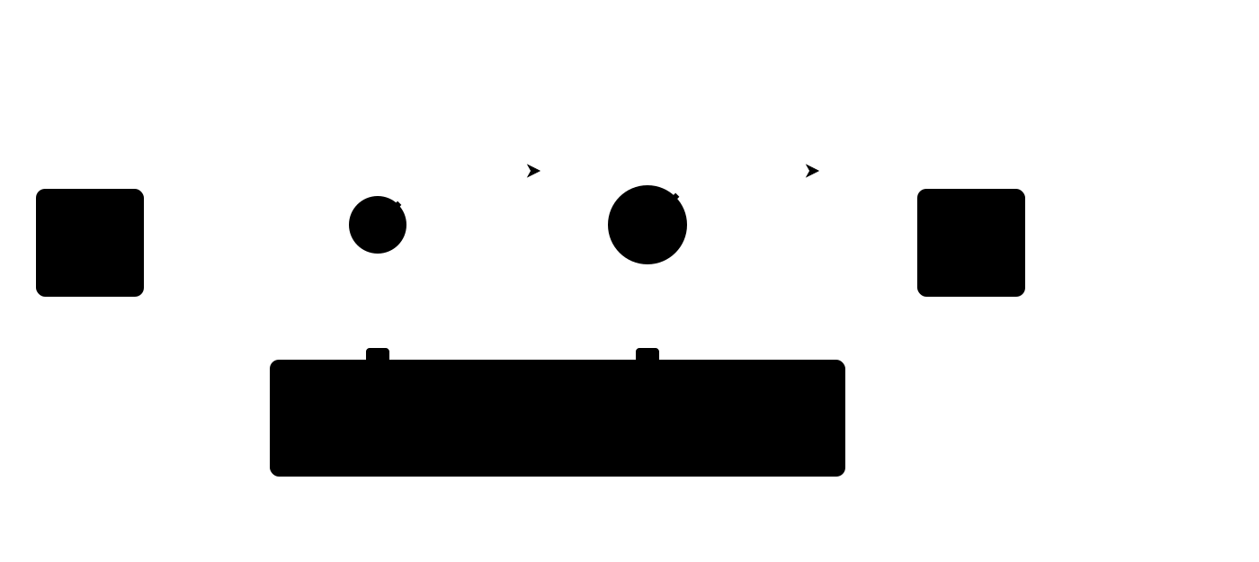
- Channel 0 — the small clamp (e.g. SCT-013-005, 5 A): sees small currents with better resolution and a lower noise floor.
- Channel 1 — the large clamp (e.g. SCT-013-030 or higher): handles currents above the small clamp's overload point without saturation.
The master itself chooses which channel to use depending on the current value — while the small clamp is in its linear range, its reading is more accurate; when it is exceeded, it switches to the large one.
Configuration
The sensor class once, then the models per channel in any order (v1.3 pure staging, order doesn't matter):
rbamp_set_sensor_class(dev, RBAMP_SENSOR_SCT013);   /* once */
rbamp_set_ct_model_ch(dev, 0, 1);   /* ch0 = SCT-013-005 (0..5 A)  — small clamp */
rbamp_set_ct_model_ch(dev, 1, 3);   /* ch1 = SCT-013-030 (0..30 A) — large clamp */
Final state: ch0 = SCT-013-005, ch1 = SCT-013-030. ✓
An alternative via rbamp_configure_channels() — one operation instead
of two:
uint8_t models[2] = { 1, 3 };   /* ch0=5A, ch1=30A */
rbamp_configure_channels(dev, RBAMP_SENSOR_SCT013, models, 2);
Aggregation logic on the master side
The simplest template is to switch on a threshold:
float read_combined_current(rbamp_handle_t dev) {
    float i_low  = NAN;
    float i_high = NAN;
    esp_err_t err_low  = rbamp_read_current(dev, 0, &i_low);   /* small */
    esp_err_t err_high = rbamp_read_current(dev, 1, &i_high);  /* large */
    /* While the small clamp is far from saturation, it gives better
     * accuracy at small currents. Switch to the large one as it
     * approaches the overload point.
     *
     * The 4.5 A threshold for the SCT-013-005 is an example value;
     * figures for low-current dual-CT use are not published. */
    if (err_low == ESP_OK && i_low < 4.5f) {
        return i_low;
    }
    return (err_high == ESP_OK) ? i_high : NAN;
}
Two clamps on one wire are physically possible on most household-gauge cables, but they require a little space in the panel.
⚙ Dual-CT figures. Figures for low-current dual-CT use (behavior near the threshold, divergence of the two clamps in the overlapping range) are not published. Treat dual-CT as a pilot pattern; for critical applications a single clamp sized to the upper load range is preferable.
Multi-channel modules — I2 and I3 (current-only)
The current-only modules for the multi-channel topology are I2 (two current channels) and I3 (three current channels). Both modules have no U-channel, so P / PF / Q calculation on the module side is impossible — they provide per-channel current (I_rms, I_peak on each channel) and nothing more.
UI2 and UI3 add the U-channel (1 U + 2 I / 1 U + 3 I), so per-channel power is computed on the module. Where only a current breakdown is needed, use I2/I3 as current sub-meters together with a separate UI1 at the service entry, which provides mains energy + voltage.
Reading channels (I2 / I3)
float i0, i1, i2;
rbamp_read_current(dev, 0, &i0);   /* ch0 */
rbamp_read_current(dev, 1, &i1);   /* ch1 */
rbamp_read_current(dev, 2, &i2);   /* ch2 — I3 only */
/* On an I variant rbamp_read_power(...) returns 0 — this is by design. */
float p_dummy; rbamp_read_power(dev, 0, &p_dummy); /* = 0.0f */
If you need active power on each sub-line, put a UI1 at the
service entry and split its total power proportionally to the per-channel
current I[k] from the I2/I3. This is the typical home deployment:
/* Pseudo-pattern: UI1 on mains, I3 on 3 sub-lines */
float p_mains_total, i0, i1, i2;
rbamp_read_power(mains_ui1, 0, &p_mains_total);
rbamp_read_current(loads_i3, 0, &i0);
rbamp_read_current(loads_i3, 1, &i1);
rbamp_read_current(loads_i3, 2, &i2);
float i_sum = i0 + i1 + i2;
if (i_sum > 0.01f) {
    float p0 = p_mains_total * i0 / i_sum;   /* approximation */
    /* ... */
}
This is an approximation: splitting by current works when the PF is roughly the same across all loads. For accurate per-load power accounting, use a UI variant (UI1 / UI2 / UI3 / UI5 / UI7) on each line.
Applications of I2 / I3
- Current sub-metering: per-circuit current breakdown, one installation point at the panel instead of a separate module per line.
- Disaggregation together with a UI1: the UI1 provides mains energy / power, and the I2/I3 break consumption down by branch (see chapter 06, scenario 1).
- Current monitoring without power accounting: overload control, load on/off detection, the I(t) profile.
- Dual-CT + a third channel (I3): a large clamp on channel 0 for a wide range, a small one on channel 1 for accuracy at small currents, the third channel for a separate auxiliary line. See the section "Advanced setup: two clamps of different ratings" above.
Power calculation on the master side:
float i;
rbamp_read_current(dev, ch, &i);
/* If the voltage is known (from a UI module upstream or fixed) */
const float U_nominal = 230.0f;
float p_estimated = U_nominal * i;   /* without PF — guaranteed overestimate */
For accurate power accounting, use a UI module (with a U-channel).
Approaches to improving sensitivity at low currents
If your load has a large dynamic range (e.g. 1 W standby for a router vs a 2000 W water heater on the same outlet), a single clamp sized to the upper limit loses the lower currents in the noise.
Three strategies in order of increasing complexity:
- Size the CT to the maximum, not "with margin". The most common mistake is to put an SCT-013-100 (100 A) on a household outlet with a typical consumption of 0.5–10 A. The signal lies in the lower 1–10 % of the sensor's range — where noise becomes comparable to the signal. For the household scenario (16 A outlet) the SCT-013-030 is optimal; for connecting a single device (≤ 5 A) the SCT-013-005.
- Dual-CT topology (requires an I2/I3 SKU — two current channels on one module): a small clamp for the lower range + a large one for the upper, with the master selecting by threshold. See the section "Dual-CT topology" above — the pattern is a pilot; figures for low-current dual-CT use are not published.
- Noise floor (factory-side): the module's calibration already
accounts for it. On the user side, nothing needs
to be done beyond
setSensorClass()+setCTModel(). Concrete accuracy figures at low currents are not published.
Production vs Factory mode (persistence reference)
The rbAmp module operates in two modes that differ in what exactly is saved to flash. The current mode is read from the corresponding module status register.
| Command (opcode) | Production | Persists |
|---|---|---|
CMD_SAVE_USER_CONFIG (0x32) |
✅ OK | ct_model / sensor_class / fleet_config / group_id / label |
CMD_COMMIT_ADDR (0x30, magic-armed) |
✅ OK | I²C address (see 04 · Wiring — changing the address) |
CMD_RESET (0x01) |
✅ OK | — (software reset) |
CMD_LATCH_PERIOD (0x27) |
✅ OK | — (period snapshot) |
CMD_CLEAR_ERROR |
✅ OK | — |
CMD_SAVE_GAINS |
❌ BLOCKED in production (returns ERR_PARAM) | gains / NF / phase (factory cal) |
CMD_FACTORY_RESET |
❌ BLOCKED in production | — |
In production mode, writes of the factory calibration (CMD_SAVE_GAINS,
CMD_FACTORY_RESET) are rejected by the firmware — this protects
against accidentally erasing the factory coefficients. Deploying
factory-mode is a manufacturer-side operation; end users don't need it.
Read-back ≠ persistence The production guard accepts a write into RAM (a subsequent read returns the written value), but the flash-save may be rejected. After a reboot the value reverts to the pre-write state. The only valid way to confirm persistence is to reboot the module via
CMD_RESETand read again:
c
rbamp_set_ct_model(dev, code);
rbamp_reset(dev);                       // CMD_RESET 0x01, works in production
vTaskDelay(pdMS_TO_TICKS(400));         // boot complete
uint8_t check; rbamp_read_ct_model(dev, 0, &check);
assert(check == code);                  // ONLY now is persistence confirmed
Cross-link: 09 · API reference — details on specific opcodes; 10 · Diagnostics — what to do if persistence is not confirmed.
What's next
- 04 · Wiring — physically connecting the clamp, arrow orientation, L/N polarity
- 05 · Quickstart — the full first-light project
- 06 · Examples — working scenarios for different loads
- 10 · Diagnostics — what to do if the readings are odd (negative PF, unstable I, etc.)
Source & issues: rb-amp/rbamp-esp-idf · this page in the repo: docs/03_sensor_selection.md (v1.7.3)