09 · YAML Schema Reference
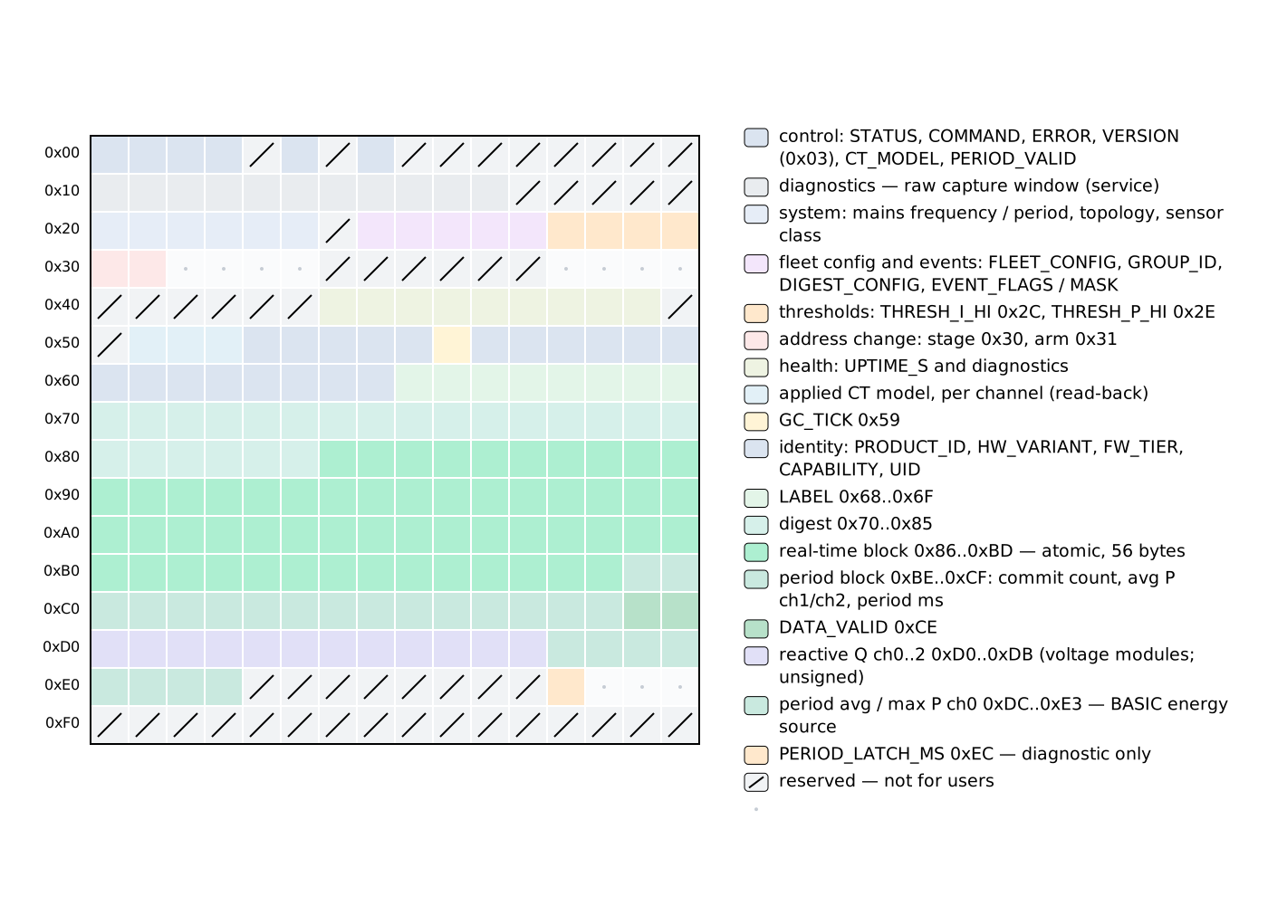
This chapter is the complete reference for the YAML schema of the rbamp external component for ESPHome. If a key is not listed here, it does not exist in the schema.
One YAML for both module lines. At boot the component identifies which module line is connected (BASIC or STANDARD (STD)) and adapts automatically: channel count, variant and available features come from the module itself, so no topology: key and no tier switch are needed in YAML. Keys that apply to only one generation are marked below; a key the connected module cannot honour is ignored with a log line, never a hard failure.
Contents:
- Component block —
rbamp: - Sensor platform —
sensor.platform: rbamp - Data flow and timing
- I2C bus settings
1. Component block — rbamp:
Native protocol: Multi-module setup (initialization) · Multi-module polling — three strategies (realtime-polling) · Multi-module issues (troubleshooting)
The top-level rbamp: block registers a component instance. It inherits from PollingComponent (which provides update_interval) and i2c.I2CDevice (which provides address and the I²C bus handle). MULTI_CONF: True means any number of rbamp: blocks can coexist in one YAML, each referencing its own I²C slave.
rbamp:
  id: meter1
  address: 0x50
  update_interval: 60s
  drdy_pin: GPIO4
  sensor_class: SCT_013
  ct_model: SCT_013_030
  # or, for a UI3 with mixed clamps:
  # ct_models: [SCT_013_005, SCT_013_030, SCT_013_020]
  bidirectional: false
  new_address: 0x51
  fleet_gc_enable: false
  group_id: 0
  latch_interval: 60s
  start_current_ua: 400     # STANDARD only, see below
  # ct_model_force: true    # service option, see below
Every key is optional. topology: and broadcast_latch: are still accepted for backward compatibility (see their entries).
id
| Attribute | Value |
|---|---|
| Type | id (ESPHome identifier) |
| Default | Auto-generated |
| Required | No |
Assigns a stable identifier to the instance. Sensors reference it via rbamp_id: meter1. With multiple rbamp: blocks, an explicit id is required.
rbamp:
  id: kitchen_meter
address
Native protocol: 02 · Initialization and Start-up (initialization) · 3.6 Canonical detection algorithm (api-reference) · 6 · Protocol sequences (api-reference)
| Attribute | Value |
|---|---|
| Type | i2c_address (7-bit, 0x08..0x77) |
| Default | 0x50 |
| Required | No |
The current I²C address of the rbAmp module. The factory default is 0x50. After applying an address change (via new_address), update this key to the new value and remove new_address.
Valid range: 0x08..0x77 (the reserved 7-bit I²C addresses are excluded).
rbamp:
  address: 0x52   # three modules on the bus: 0x50, 0x51, 0x52
Cross-reference: the I²C bus protocol in the API reference; runtime address change for changing the address after boot.
update_interval
Native protocol: 04 · Period Metering and Tariff Accounting (period-metering) · Continuous polling cycle (recommended) (period-metering) · Period snapshot registers (period-metering)
| Attribute | Value |
|---|---|
| Type | time (ESPHome duration string) |
| Default | 60s |
| Required | No |
How often update() runs. Each call:
- Sends the snapshot command and schedules a non-blocking 50 ms timeout for reading the period snapshot (BASIC modules; on STANDARD modules energy comes from the module's own counters, see
energy_total). - Checks the status register; if the module is ready, publishes all bound instantaneous sensors.
The 60 s default is reasonable: the module internally updates its period-average power roughly every ~100 ms, but integrating energy on the master side requires a long enough window to be correct. At 60 s and an average load of 60 W, a missed snapshot loses ≤ 1 Wh.
The minimum allowed value is 1s: the schema rejects anything smaller, and esphome config reports a diagnostic.
Values below 5-10 s offer no benefit for tight synchronization and just clutter
the bus.
rbamp:
  update_interval: 30s   # more frequent dashboard updates, more traffic
latch_interval
Native protocol: Continuous polling cycle (recommended) (period-metering) · 4.11 V03 period block (0xBE..0xCF) (api-reference) · 6.4 Period sync — two strategies (api-reference)
| Attribute | Value |
|---|---|
| Type | time (ESPHome duration string) |
| Default | Same as update_interval |
| Required | No |
| Since | v1.4 |
How often the component sends the snapshot command and integrates a Wh sample. When set, decouples the snapshot cycle from the RT-read cadence — update_interval: continues to control how often V/I/P/PF/Q registers are read and published, while latch_interval: controls how often the period accumulator is snapshotted and Wh is integrated.
Energy integration adds no error of its own beyond the module's active-power accuracy, regardless of the ratio: master-side integration uses the actual wall-clock dt between successive snapshot events, so longer snapshot intervals just produce coarser integration steps.
Must be >= update_interval (setting it shorter is rejected at config validation — the extra snapshots would produce no observable data).
When unset, snapshot runs on every update() call (v1.3 single-cadence behaviour, backwards-compatible).
rbamp:
  update_interval: 3s        # RT V/I/P/PF refreshed every 3 s
  latch_interval: 60s        # snapshot + Wh integration once a minute
Useful when bus load or master-side CPU competition matters — multi-module fleets, ESP8266 hosts (single-core; WiFi ISRs compete for CPU during I²C transactions), or shared I²C buses with other devices.
drdy_pin
Native protocol: 01 · Hardware Connection (hardware-connection) · 03 · Real-Time Polling (realtime-polling)
| Attribute | Value |
|---|---|
| Type | gpio_input_pin_schema |
| Default | None (optional) |
| Required | No |
Connects the module's open-drain DRDY output to a GPIO on the ESP32. When specified, the pin is configured in setup() at boot.
The pin is logged in
dump_configbut is not used as a read trigger — the instantaneous registers are polled onupdate_interval. Declaring the pin does not change behavior.
rbamp:
  drdy_pin: GPIO4
sensor_class
Native protocol: Setting the sensor class and CT model (initialization) · 4.3 System (0x20..0x25) (api-reference) · 6.2 CT model binding — pure staging + per-channel CMD (api-reference)
| Attribute | Value |
|---|---|
| Type | enum (SCT_013, WIRED_CT, BUILTIN_CT) |
| Default | SCT_013 |
| Required | No |
Fixes the current-sensor family on the module side. On firmware v1.2+ the value is written to flash and becomes a precondition for writing the CT model: the module will refuse to write the model if the class is not set. On earlier firmware the value is accepted by the schema and is applied automatically on upgrade.
| Value | Meaning |
|---|---|
SCT_013 |
Split-core SCT-013 clamps — the default |
WIRED_CT |
Module supplied calibrated together with its own fitted sensor |
BUILTIN_CT |
Module supplied calibrated together with its own built-in sensor |
Write guard. The component never writes a class the module already has (a repeat boot writes nothing). On a module that was calibrated as a pair with its fitted sensor (WIRED_CT / BUILTIN_CT), a class or model change from YAML is refused with an explicit log line — the write would replace the individual calibration with a generic setting. Leave sensor_class: and ct_model: out of the YAML for such modules, or see ct_model_force.
rbamp:
  sensor_class: SCT_013   # default; may be omitted
For more on choosing the clamp and family, see 03_sensor_selection.md.
ct_model
Native protocol: Setting the sensor class and CT model (initialization) · 6.2 CT model binding — pure staging + per-channel CMD (api-reference) · 8.6 Fresh-flash provisioning (api-reference)
| Attribute | Value |
|---|---|
| Type | enum (SCT_013_005, _010, _020, _030, _050) |
| Default | None (optional) |
| Required | No |
Writes the CT clamp model identifier to the module's flash. On firmware v1.2+ this automatically loads the factory coefficients for the chosen model — no additional calibration steps are required. A value equal to what the module already has is not written.
| YAML value | Code | Nominal current | Status v1.3 |
|---|---|---|---|
SCT_013_005 |
1 | 5 A | production |
SCT_013_010 |
2 | 10 A | production |
SCT_013_020 |
6 | 20 A | production (new in v1.3) |
SCT_013_030 |
3 | 30 A | production (default SKU) |
SCT_013_050 |
4 | 50 A | production |
The per-class accept-set for
SCT_013is{1, 2, 3, 4, 5, 6, 7}(SCT_013_100is code 5,SCT_013_060is code 7; the code order is not the rating order). Non-matching values are rejected atesphome configviacv.Invalid. For more, see 03 · Current-sensor selection.
rbamp:
  ct_model: SCT_013_030
Applied once in setup(). Each write is accompanied by a ~700 ms flash-write (the module NACKs all I²C operations during this time — the component feeds the watchdog automatically).
Changing the SCT rating keeps the accuracy. Every SCT module is calibrated at the factory with the SCT-013-030. When you select another rating, current, power and energy stay correct: on firmware up to 1.4.19 the component completes the model write with a module restart (this is part of the normal flow and shows in the log), then scales readings to the selected sensor; newer firmware performs the switch on the module and the component leaves the readings untouched. Voltage and power factor are not affected. No YAML change is needed for this.
Write guard. An equal value is never written, and on a factory-paired module (sensor_class: WIRED_CT / BUILTIN_CT) the write is refused with a log line — see sensor_class.
Mutually exclusive with ct_models: — only one of the two may be used per rbamp: block.
For more, see 03_sensor_selection.md. Cross-reference: the ct_model reference.
ct_models
| Attribute | Value |
|---|---|
| Type | list of 1–16 enum values |
| Default | None (optional) |
| Required | No |
Per-channel CT clamp models — for modules with mixed clamps on different channels. Accepts the same enum values as ct_model:. The schema accepts 1 to 16 entries; the position in the list is the channel index. The component applies as many entries as the module has channels (1 for UI1, 2 for UI2, 3 for UI3, and so on); extra entries are ignored with a warning.
rbamp:
  id: ui3_meter
  ct_models: [SCT_013_005, SCT_013_030, SCT_013_020]
  # CH0=5A for standby loads (maximum resolution),
  # CH1=30A for main household loads,
  # CH2=20A for a water heater / medium-power branch (~3-5 kW)
  # For currents above 50 A use SCT_013_060 (60 A) or SCT_013_100 (100 A)
On firmware v1.2+ each channel gets its own set of factory coefficients independently. The total setup time at boot is ~2-3 seconds (~700 ms flash-write per channel).
STANDARD modules. Per-channel models are stored only by modules that advertise persistent per-channel storage. On a module that does not, the component refuses loudly (a warning that ct_models: is not supported by this device, keys ignored) instead of writing a value that would silently revert after a power cycle — use the single ct_model: there.
The same write guards as for ct_model: apply (equal values are not written; factory-paired modules refuse the change).
Mutually exclusive with ct_model:.
ct_model_force
| Attribute | Value |
|---|---|
| Type | bool |
| Default | false |
| Required | No |
Service option. Overrides the write guard: the component then applies the ct_model: / ct_models: preset even when the module is factory-paired or already holds the same value. This replaces the module's individual calibration with the generic preset for that model, so use it only deliberately, run it once and remove it.
The schema rejects ct_model_force: true unless ct_model: or ct_models: is also present, so the flag cannot sit armed in YAML waiting for a later model line.
rbamp:
  ct_model: SCT_013_030
  ct_model_force: true   # one-off; remove both lines after the operation
start_current_ua
| Attribute | Value |
|---|---|
| Type | integer, microamps |
| Allowed values | 0 (off) or 10..2540 in steps of 10 |
| Default | None (the module's own default applies) |
| Required | No |
| Applies to | STANDARD modules with on-device energy counters; ignored with a warning elsewhere |
Starting current for energy accounting. While a channel's current is below this value, the module counts no energy on that channel. Without it, at no load the measured power is noise of either sign and slowly creeps into both the import and the export counters. Instantaneous readings (current, power, ...) are not affected — only the energy counters.
Values outside the allowed set (for example 15 or 3000) are rejected by the schema, so an invalid value never reaches the bus. The setting is stored on the module and verified after the write; a value equal to the stored one is not rewritten.
rbamp:
  start_current_ua: 400
You can read the stored value back from a lambda with id(meter1).read_start_current_ua() (returns 65535 when unavailable).
period_banks
| Attribute | Value |
|---|---|
| Type | list of bank entries |
| Entries per list | 1..8, each bank: (0..7) listed once |
| Default | None |
| Required | No |
| Applies to | STANDARD modules that advertise snapshot banks (image 0x7E and later); on any other module the entries stay unavailable and the log says so once at boot |
The module keeps eight independent snapshot banks. Each entry measures one period — the time between two latches of the same bank, timed by the ESP32's clock — and publishes the period's averages, peaks and energy. Use it for "energy per hour", "peak current since the last press" and similar questions that the running totals do not answer.
| Key | Meaning |
|---|---|
bank |
Bank number 0..7. Bank 0 is free on modules with on-device energy counters; on a module without counters the component uses bank 0 itself and the entry is ignored with a warning. |
interval |
Optional automatic latch cadence, at least 1s. Without it the bank is latched only by the rbamp.latch_bank action. |
power, reactive_power, apparent_power |
Average over the period. |
energy, energy_exported |
Wh imported / exported in the period (not meters — they carry state_class: measurement). |
max_power, max_current, max_voltage, min_voltage |
Extremes inside the period. |
period_length |
The period length in seconds, as measured by the ESP32. |
channels |
Optional list, one entry per current channel (first entry = channel 0), each with power, energy, energy_exported. |
The first latch of a bank after boot, or after the module restarts, only starts the period; its values are dropped and sensors publish from the next latch on. Latches of different banks are kept at least 150 ms apart.
rbamp:
  id: meter1
  period_banks:
    - bank: 1
      interval: 1h
      power: {name: "Hour average power"}
      energy: {name: "Hour energy"}
      max_current: {name: "Hour peak current"}
    - bank: 2                    # latched by hand
      energy: {name: "Energy since last press"}
      period_length: {name: "Since last press, s"}
button:
  - platform: template
    name: "Latch bank 2"
    on_press:
      - rbamp.latch_bank:
          id: meter1
          bank: 2
A complete example is in example/std_banks.yaml.
bidirectional
Native protocol: Bidirectional accounting (period-metering)
| Attribute | Value |
|---|---|
| Type | bool |
| Default | false |
| Required | No |
Enables the per-channel export-energy path (energy_exported, energy_exported_1, energy_exported_2). When true, export energy is accumulated separately from import energy.
On a STANDARD module the export energy is taken from the module's own counters, so it survives restarts and is monotonic. On a BASIC module the line is unidirectional: the energy_exported_* sensors are accepted by the schema but publish 0.
Declare energy_exported (or _1 / _2) under sensor.platform: rbamp only when bidirectional: true is set. The grand-total sensors energy_exported_total and energy_net do not need this key.
rbamp:
  bidirectional: true   # needed for the per-channel energy_exported* sensors
new_address
Native protocol: Address change (initialization) · 4.5 Address (0x30..0x31) (api-reference) · 6.1 Address change — two-phase commit (production-OK) (api-reference)
| Attribute | Value |
|---|---|
| Type | i2c_address (0x08..0x77) |
| Default | None (optional) |
| Required | No |
Triggers a one-time I²C address change at boot. It must differ from address — the validator raises an error if they are equal.
On firmware v1.3 a two-phase commit is used — production-OK without factory-provisioning gating. Compatibility behavior:
| Firmware | Behavior |
|---|---|
| Advertises two-phase address commit (v1.3+) | Production path — staged write, explicit confirmation, commit, re-enumeration. |
| Does not advertise it (legacy v1.0-v1.2) | Legacy fallback — single-phase write, requires factory-provisioning mode. Logs WARN_FACTORY_MODE_REQUIRED if not in provisioning. |
STANDARD modules support new_address: as well; the component applies it and re-binds to the new address the same way.
The full flow runs once in setup():
- Probe the current
address. If the module does not respond there but does respond atnew_address, the component adapts to the new address with a warning (assuming a previous boot already applied the change) and skips the write. - Check whether the firmware advertises two-phase commit. Yes → production path (see below). No → legacy path with the provisioning-mode check.
- Production path (v1.3): stage the new address, confirm, commit → wait ~700 ms → re-probe
new_address. No factory-mode gating is required. - Legacy path (v1.0-v1.2): single-phase write, requires factory-provisioning mode on the module side.
- The component switches its internal I²C address via
i2c::I2CDevice::set_i2c_address()tonew_addressand verifies that the module responds. - If the module does not respond after the change, the component calls
mark_failed()and stops.
After a successful change: update the YAML to address: <new> and remove new_address:. If the module is at the new address on the next boot but new_address: is still in the YAML, the boot-time probe of the old address fails, the probe of the new address succeeds, the component adapts with a warning, and no re-write happens.
⚠ Factory-mode-only on legacy firmware (v1.0-v1.2).
Standard production modules on legacy firmware shipped with provisioning mode disabled. Writing
new_address:to such a module without factory mode will be rejected (warningWARN_FACTORY_MODE_REQUIRED). On v1.3 firmware this restriction is gone — the component detects the production-OK path automatically.⚠ Re-enumeration after commit. After a successful commit the module resets and re-enumerates at the new address. Subsequent calls within the same
setup()are directed to the new address transparently — but any other master on the bus (a raw I²C tool, a debug probe, another ESP32) still considers the module to be at the old address until it updates its own state.
rbamp:
  address: 0x50
new_address: 0x51 # remove this line after the first successful bootRecovery: if the address change was applied but the module does not respond, see 10_troubleshooting.md → "Address changed, but the module doesn't respond".
Cross-reference: the runtime address change reference.
fleet_gc_enable (v1.3 NEW)
Native protocol: General Call (broadcast at address 0x00) (initialization) · Multi-module — simultaneous snapshot (period-metering) · 4.4 Fleet config (0x27..0x2F) (api-reference)
| Attribute | Value |
|---|---|
| Type | bool |
| Default | false |
| Required | No |
| Applies to | BASIC modules with general-call snapshot support (v1.3+ firmware); ignored with a log line on STANDARD |
Opt-in: enables receipt of the General-Call snapshot broadcast from the master. When
the ESP32 emits a 5-byte GC frame to address 0x00, all modules with fleet_gc_enable:
true (and a matching group_id:) atomically take a snapshot of their period accumulators
at a single wire moment. This delivers tight synchronization between
sub-meters.
Capability behavior: at boot the component checks whether the firmware advertises general-call snapshot. If it does not → warning + skip without apply:
[W][rbamp:xxx]: fleet_gc_enable requested but the module does not advertise general-call latch;
firmware v1.0-v1.2 doesn't support General-Call. Falling back to sequential
latch (~270 µs × N inter-module skew at 50 kHz).Persistence: on apply the component writes REG_FLEET_CONFIG.bit0,
saves to flash via CMD_SAVE_USER_CONFIG, and RESETs the device — GC mode
is configured at init time, not toggleable live. Via read-compare-write
this happens once on the first boot; subsequent boots skip it.
rbamp:
- id: mains
fleet_gc_enable: true # opt-in, capability-gated
group_id: 1 # see below
- id: boiler
fleet_gc_enable: true
group_id: 1 # same group → synchronizedCross-reference: the Fleet Group-Commit reference, 04_hardware.md Multi-module fleet.
group_id (v1.3 NEW)
Native protocol: General Call (broadcast at address 0x00) (initialization) · Multi-module — simultaneous snapshot (period-metering) · 4.4 Fleet config (0x27..0x2F) (api-reference)
| Attribute | Value |
|---|---|
| Type | uint8_t (0..255) |
| Default | 0 |
| Required | No |
| Applies to | BASIC modules; ignored with a log line on STANDARD |
A cluster identifier for selective GC snapshot. The module accepts a GC frame
only if the group field in the frame matches this group_id OR equals
0x00 (all-call).
Use cases:
- Multi-tenant: one ESP32 drives several independent clusters of
modules (e.g. 3 apartments in one panel). Cluster 1 =
group_id: 1, cluster 2 =group_id: 2. The master emits a GC frame with group=1 → only cluster 1 takes a snapshot. - Single-tenant: leave
group_id: 0(all-call) or setgroup_id: 1as a label — the behavior is identical, all modules take a snapshot.
Persistence: written to REG_GROUP_ID and saved to flash via
read-compare-write. Changing it requires a boot.
rbamp:
  - id: apt1_mains
    group_id: 1
  - id: apt2_mains
    group_id: 2
broadcast_latch (deprecated, v0.4.0 legacy)
| Attribute | Value |
|---|---|
| Type | bool |
| Default | false |
| Required | No |
| Status | Deprecated — replaced by fleet_gc_enable: (v1.3+). |
A legacy alias for the General-Call broadcast snapshot. In v1.3 this key is accepted
by the schema as a no-op (for non-breaking migration from v0.4.0 YAML), but it has
no effect. For new code, use fleet_gc_enable: — it is capability-gated
and works on v1.3 firmware.
It will be removed in a future minor release; a deprecation warning appears in the log:
[W][rbamp:xxx]: 'broadcast_latch:' is deprecated since v1.3 — use
'fleet_gc_enable:' instead. This key has no effect.
Cross-reference: the Fleet Group-Commit reference.
topology
| Attribute | Value |
|---|---|
| Type | enum (SINGLE, SPLIT_PHASE, THREE_PHASE) |
| Default | SINGLE |
| Required | No |
Optional hint, kept for backward compatibility. It is not needed on STANDARD modules: the component reads the channel count, variant and capabilities from the module itself and sizes the entity set from that. On BASIC modules the channel count is derived from the current[_1/_2] slots you declare, and topology: only changes the line printed by dump_config.
rbamp:
  topology: SINGLE         # cosmetic; may be omitted
2. Sensor platform — sensor.platform: rbamp
Each sensor: block declares one set of named sensors bound to the parent rbamp: component. The only required key in the block is rbamp_id.
sensor:
  - platform: rbamp
    rbamp_id: meter1
    voltage:
      name: "Mains Voltage"
    current:
      name: "Mains Current"
    power:
      name: "Mains Power"
    energy:
      name: "Mains Energy"
    frequency:
      name: "Mains Frequency"
    power_factor:
      name: "Mains Power Factor"
All fields under the sensor: block are optional, with one rule: power, energy, power_factor, reactive_power and apparent_power need voltage AND current declared in the same block (the numbered channel sensors power_N, energy_N, power_factor_N, reactive_power_N need current_N and voltage); otherwise esphome config fails with "power requires current to also be declared". Add internal: true to a required sensor you do not want as a Home Assistant entity. Declare only the quantities your scenario needs — the component reads only the registers that correspond to the declared sensors.
rbamp_id
| Attribute | Value |
|---|---|
| Type | use_id(RbAmpComponent) |
| Required | Yes |
References the rbamp: block this sensor group is bound to.
2.1 Single fields
Native protocol: Multi-channel current (UI2 / UI3 / UI5 / UI7) (realtime-polling) · 4.14 Channel access window (
0x32+0x3C..0x3F) (api-reference)
Used for single-voltage modules (UI1, UI2, UI3, I1, I2, I3 and higher-channel variants). All fields are optional. Mixing them with phased fields (voltage_a, voltage_angle_b, etc.) raises a validation error.
Slots exist for up to seven current channels: current and current_1 ... current_6, and likewise power, energy and power_factor with the same suffixes (power_3, energy_5, ...). energy_exported exists for channels 0..2 (energy_exported, energy_exported_1, energy_exported_2). A slot beyond the channel count the module reports never publishes. reactive_power exists for channels 0..2 only (reactive_power, reactive_power_1, reactive_power_2); reactive_power_3 ... reactive_power_6 are accepted by the schema but never publish.
Each field accepts the standard ESPHome sensor.sensor_schema subkeys: name, id, filters, unit_of_measurement, accuracy_decimals, icon, and so on.
voltage
Native protocol: RT register reference (realtime-polling) · 4.10 V03 real-time block (0x86..0xBD) (api-reference)
| Attribute | Value |
|---|---|
| Unit | V |
device_class |
voltage |
state_class |
measurement |
accuracy_decimals |
1 |
| Source | RMS mains voltage (instantaneous module register) |
RMS mains voltage. Read on every update() once the module is ready. The 4-byte float is read with per-byte retry (3 attempts × 5 ms) and passes a std::isfinite() check plus |val| < 10000.
Zero is a valid value to publish: a mains-outage or brownout event yields U ≈ 0 V and passes through to HA without filtering — the sanity filter only discards NaN/Inf, not legitimate zeros.
voltage:
  name: "Mains Voltage"
  filters:
    - sliding_window_moving_average:
        window_size: 3
        send_every: 1
current / current_1 ... current_6
| Attribute | Value |
|---|---|
| Unit | A |
device_class |
current |
state_class |
measurement |
accuracy_decimals |
3 |
RMS current for channels 0, 1, 2, ... Channel 0 is the main CT clamp; channels 1 and 2 are present on the UI2 / UI3 and I2 / I3 variants, channels 3..6 on higher-channel variants.
On a BASIC module the active channel count is derived from the number of declared slots: if only current is declared, the component uses 1 channel; with current and current_1, 2; adding current_2 gives 3. On a STANDARD module the channel count comes from the module itself; declared slots beyond it simply never publish.
current:
  name: "Phase Current"
current_1:
  name: "Load 1 Current"
current_2:
  name: "Load 2 Current"
power / power_1 ... power_6
Native protocol: RT register reference (realtime-polling) · 4.10 V03 real-time block (0x86..0xBD) (api-reference)
| Attribute | Value |
|---|---|
| Unit | W |
device_class |
power |
state_class |
measurement |
accuracy_decimals |
1 |
| Dependencies | power requires current + voltage; power_N requires current_N + voltage |
Active power in watts, signed. Negative values = reverse flow (generation into the grid) on STANDARD modules. On BASIC, negative instantaneous values within the period window are clamped to 0 at the firmware level — the period average is ≥ 0. The instantaneous active power can still read negative at the moment of generation.
Declaring power without current + voltage raises a validation error:
power requires current to also be declared.
power:
  name: "Active Power"
energy / energy_1 ... energy_6
Native protocol: Master-side algorithm (period-metering) · 7 · Semantics (api-reference)
| Attribute | Value |
|---|---|
| Unit | Wh |
device_class |
energy |
state_class |
total_increasing |
accuracy_decimals |
3 |
| Dependencies | energy requires current + voltage; energy_N requires current_N + voltage |
Accumulated consumed (import) energy in Wh for the channel.
- STANDARD modules — the component accumulates the module's own energy counters. Totals survive restarts of both the ESP32 and the module and are monotonic (they do not step back when the module restarts or a counter is reset).
- BASIC modules — computed on the ESP32 from the period-average power returned by the module after each snapshot:
E_Wh[ch] += avg_P_W[ch] * master_dt_s / 3600In both cases the value is saved to the ESP32 flash (NVS) every 5 minutes and on a clean shutdown (reboot / OTA), and restored before the first publish_state at boot — this keeps the HA Energy dashboard from interpreting an instantaneous 0 as a counter reset. On BASIC, a sudden power failure loses at most the last 5 minutes of energy (≈ 5 Wh at an average of 60 W). When the NVS layout changes (a version bump), the counter starts from 0.
state_class: total_increasing is required for the HA Energy dashboard. The value rises monotonically; it does not decrease under normal operation.
energy:
  name: "Mains Energy"
energy_exported / energy_exported_1 / energy_exported_2
Native protocol: Bidirectional accounting (period-metering)
| Attribute | Value |
|---|---|
| Unit | Wh |
device_class |
energy |
state_class |
total_increasing |
accuracy_decimals |
3 |
| Dependencies | Requires current + voltage + bidirectional: true |
Export (generation) energy in Wh for channels 0..2, accumulated separately from energy. Set bidirectional: true in the rbamp: block when declaring these sensors. On STANDARD modules the values come from the module's counters (persistent, monotonic). On BASIC modules the sensors are accepted but publish 0.
power_factor / power_factor_1 ... power_factor_6
| Attribute | Value |
|---|---|
| Unit | (dimensionless) |
device_class |
power_factor |
state_class |
measurement |
accuracy_decimals |
3 |
| Dependencies | Requires current + voltage for the corresponding slot |
Power factor in the range −1..+1. A negative PF means a leading or lagging load; the sign convention is defined by the firmware. The sanity filter (§B.5) discards values outside |pf| > 10000; there is no lower bound.
power_factor:
  name: "Power Factor"
reactive_power / reactive_power_1 / reactive_power_2
Native protocol: 4.12 V03 Q + period ch0 (0xD0..0xE3, production build) (api-reference)
| Attribute | Value |
|---|---|
| Unit | VAr |
device_class |
reactive_power |
state_class |
measurement |
accuracy_decimals |
1 |
| Dependencies | Requires current + voltage for the corresponding slot |
Reactive power in var. Unsigned (≥ 0), computed as √(S² − P²), includes distortion; no accuracy stated. Inductive and capacitive loads are not distinguished. Read from the module on every update() cycle; published for channels 0..2 only (reactive_power_3 ... reactive_power_6 are accepted by the schema but never publish). No accuracy is stated for reactive power.
reactive_power:
  name: "Reactive Power"
Note on
device_class: reactive_power— ESPHome accepts it (theDEVICE_CLASS_REACTIVE_POWERconstant), and the value passes through to Home Assistant. However, Home Assistant's officialdevice_classlist has changed over time: in some versionsreactive_poweris available in the UI and works with the unit_of_measurementVAr, while in others it is displayed as a generic sensor with no specialized icon or unit conversion. The data itself is always published (it is just astate); the only question is how HA renders the sensor in Lovelace. If the sensor shows up as unknown in your HA version, that is cosmetic, not a functional regression. Remove thereactive_power:key from the YAML if you do not use the sensor.
apparent_power
| Attribute | Value |
|---|---|
| Unit | VA |
device_class |
apparent_power |
state_class |
measurement |
accuracy_decimals |
1 |
| Source | Computed on the master: S = V_rms × I_rms[0] |
| Dependencies | Requires current + voltage |
Apparent power in VA. Computed by the component from the U_rms and I0_rms values read in the same update() cycle — no separate register is read. Both reads must succeed in the same cycle; if even one fails (retry exhausted), no state is published in that cycle and the last value in HA is preserved.
apparent_power is in SHARED_FIELDS and works with any topology, but it depends on voltage and current for the V × I computation.
apparent_power:
  name: "Apparent Power"
2.2 Phased fields (multi-voltage variants)
For modules with more than one voltage input (split-phase and three-phase variants) the sensors are declared per phase. The schema accepts the phased group on any module; a slot publishes only when the connected module actually reports the corresponding channel, otherwise it stays without a value.
Single and phased fields are mutually exclusive within one sensor: block. The validator raises an error:
Cannot mix single-phase fields (voltage, current, current_1, ...) with
phased fields (voltage_a/b/c, current_a/b/c, ...).
All phased fields share the same sensor_schema defaults as their single-phase counterparts (the same units, device_class, state_class, accuracy_decimals).
| Field | Unit | device_class |
|---|---|---|
voltage_a / _b / _c |
V | voltage |
current_a / _b / _c |
A | current |
power_a / _b / _c |
W | power |
power_total |
W | power |
energy_a / _b / _c |
Wh | energy |
energy_exported_a / _b / _c |
Wh | energy |
power_factor_a / _b / _c |
— | power_factor |
reactive_power_a / _b / _c |
VAr | reactive_power |
voltage_angle_b / _c |
° | — |
voltage_angle_b and voltage_angle_c publish the phase angle of the B and C voltages in degrees, relative to phase A (phase A is the 0° reference, so there is no voltage_angle_a). They need a module firmware that provides the angles; on older firmware the component logs a warning at boot and the sensors never publish. While the angle cannot be determined the value is "unknown".
Per-phase dependency validation is not enforced for phased fields (only
_SINGLE_SLOT_DEPSfor single-phase).
Example:
rbamp:
  id: panel_meter
  address: 0x50
sensor:
  - platform: rbamp
    rbamp_id: panel_meter
    voltage_a:
      name: "Phase A Voltage"
    voltage_b:
      name: "Phase B Voltage"
    voltage_c:
      name: "Phase C Voltage"
    current_a:
      name: "Phase A Current"
    current_b:
      name: "Phase B Current"
    current_c:
      name: "Phase C Current"
    power_total:
      name: "Total Active Power"
    voltage_angle_b:
      name: "Phase B Angle"
    voltage_angle_c:
      name: "Phase C Angle"
2.3 Shared fields (topology-independent)
These fields work in any topology group, including the case where no single-phase or phased current sensor is declared at all (a voltage-only or frequency-only deployment).
frequency
| Attribute | Value |
|---|---|
| Unit | Hz |
device_class |
frequency |
state_class |
measurement |
accuracy_decimals |
0 |
Mains frequency. Implausible values (module reports "not measured yet") are discarded without publishing, which avoids an "Unknown" → 0 Hz → 50 Hz transition in the HA entity during warm-up.
frequency:
  name: "Mains Frequency"
apparent_power
See the entry under the single fields above. apparent_power requires current and voltage, so it belongs in a single-phase sensor block.
energy_total / energy_exported_total / energy_net
| Sensor | Unit | state_class |
Meaning |
|---|---|---|---|
energy_total |
Wh | total_increasing |
Imported energy, all channels of the module |
energy_exported_total |
Wh | total_increasing |
Exported energy, all channels of the module |
energy_net |
Wh | total |
Import minus export. May decrease. |
Grand totals over all channels of the module, taken from the module's own energy counters (STANDARD modules). They survive restarts of the ESP32 and of the module, are monotonic across module restarts and counter resets (except energy_net, which is the difference of two monotonic values), and are also saved to NVS every 5 minutes and on a clean shutdown. They need no bidirectional: key and no companion current/voltage declaration.
On a module without on-device energy counters (BASIC) these keys validate but never publish; the component logs a warning at boot. Use the per-channel energy sensors there.
sensor:
  - platform: rbamp
    rbamp_id: meter1
    energy_total:
      name: "Energy Imported"
    energy_exported_total:
      name: "Energy Exported"
    energy_net:
      name: "Energy Net"
reactive_energy / reactive_energy_exported
| Attribute | Value |
|---|---|
| Unit | varh |
state_class |
total_increasing |
accuracy_decimals |
3 |
Reactive energy (import / export) over all channels, from the same on-device counters and with the same persistence as energy_total. STANDARD modules only; on others the keys validate but never publish.
phase_sequence
| Attribute | Value |
|---|---|
| Unit | — |
accuracy_decimals |
0 |
Phase rotation of a three-voltage module: 1 = forward, 2 = reverse, 3 = abnormal. "Unknown" while it cannot be determined (fewer than three live voltage inputs). Needs a module firmware that provides it; otherwise the component logs a warning at boot and the sensor never publishes. In a lambda, id(meter1).get_phase_sequence_str() returns "forward", "reverse", "abnormal", "n/a" or "unavailable".
2.4 Schema validation rules
The Python validator _validate_topology_consistency applies two classes of rules during esphome config / compile time — before any C++ code runs.
Topology mutual exclusion
Single-phase fields (voltage, current, current_1, etc.) and phased fields (voltage_a, voltage_b, etc.) cannot coexist in one sensor: block. An attempt to mix them:
Cannot mix single-phase fields (voltage, current, current_1, ...) with
phased fields (voltage_a/b/c, current_a/b/c, ...). Pick one group based
on your rbAmp SKU.
The phased group includes voltage_angle_b / voltage_angle_c.
Per-slot companion requirements (single-phase only)
Each derived field requires the input fields the module needs to compute it:
| Declared field | Required companions |
|---|---|
power / _1 ... _6 |
current (or _1 ... _6, same suffix) + voltage |
energy / _1 ... _6 |
current (or _1 ... _6, same suffix) + voltage |
power_factor / _1 ... _6 |
current (or _1 ... _6, same suffix) + voltage |
reactive_power / _1 / _2 |
current (or _1 ... _6, same suffix) + voltage |
apparent_power |
current + voltage |
energy_exported*, energy_total, energy_exported_total, energy_net, reactive_energy* and phase_sequence have no schema companion requirements.
A missing companion raises:
`power` requires `current` to also be declared — the underlying chip
cannot compute it without that input.
Other rules at the rbamp: block level
| Rule | Description |
|---|---|
ct_model: ↔ ct_models: mutually exclusive |
Only one of the two may be used per rbamp: block — otherwise a validation error. |
new_address ≠ address |
If they match — cv.Invalid. |
address in the range 0x08..0x77 |
cv.i2c_address is applied. |
update_interval ≥ 1s |
Shorter intervals are rejected. |
latch_interval ≥ update_interval |
A shorter snapshot cadence is rejected. |
ct_models: has 1..16 entries |
Longer lists are rejected. |
group_id is 0..255 |
Out-of-range values are rejected. |
start_current_ua is 0 or 10..2540 in steps of 10 |
Any other value is rejected. |
ct_model_force: true requires ct_model: or ct_models: |
Rejected on its own. |
period_banks: — each bank once, interval ≥ 1s |
A duplicate bank, a bank outside 0..7 or a shorter interval is rejected. |
CT model code valid for the pinned sensor_class |
A code not allowed for the class is rejected with the list of allowed values. |
All validation errors are reported during esphome compile with a human-readable message pointing at the offending key. There is no need to flash hardware to find a configuration error.
3. Data flow and timing
Native protocol: Polling — single module (realtime-polling) · 3.
DATA_VALID(0xCE) never becomes 1 (troubleshooting) · 4 · Register map (production v1.3) (api-reference)
The conceptual flow of a single update() cycle:
Module (autonomous)                  ESP32 (ESPHome component)
─────────────────────────────────   ────────────────────────────────────────────
Measures & computes the
instantaneous block (RMS / P / PF / Q)
  ↓ (~100 ms per cycle)
Atomically publishes the block       update() fires every update_interval (60 s)
of instantaneous registers            ↓
  ↓                                 phase 1 — snapshot:
                                      write the snapshot command
Closes the period accumulator,        50 ms timeout (non-blocking)
opens a new one                       ↓ (main loop keeps running)
  ↓
  wait 50 ms                        phase 2 — period snapshot:
                                      read the valid flag
                                      read per-channel average powers
                                      E_Wh[ch] += avg_P × dt_s / 3600
                                      save to NVS if 5 minutes elapsed
                                      ↓
                                    phase 3 — instantaneous values:
                                      read the status register
                                      read U_rms, I[0..n]_rms, P[0..n],
                                            PF[0..n], Q[0..n], frequency
                                      publish all bound sensors
                                      ↓
                                    Push state to HA over the native API
The diagram shows the BASIC snapshot-based flow. A STANDARD module keeps its own energy counters: on each
update()the component reads the instantaneous values and the counter snapshot (one coherent transaction) and adds the difference to its running totals, so the snapshot step is not used for energy.
Characteristic timings:
| Event | Cadence |
|---|---|
| Internal commit of the instantaneous block by the module | ~100 ms |
update() call |
update_interval (60 s by default) |
| Settle timeout after the snapshot command | 50 ms (non-blocking) |
| Save to NVS | Every 5 minutes |
| Pause between per-byte retries | 5 ms, up to 3 attempts |
| Flash-write window when writing the model | ~700 ms (the module NACKs the whole time) |
The snapshot-settle timeout is non-blocking — the cooperative ESPHome scheduler keeps servicing WiFi, the API, and other components during the 50 ms wait. The remaining update() phases (reading the instantaneous registers) run immediately after returning from the snapshot phase.
The warning [W][component:522]: rbamp took a long time for an operation (XXX ms) is expected and harmless when it does appear. On v1.3 firmware the component reads the instantaneous-values block via a single burst read (READ auto-increment), so a healthy cycle stays well under 30 ms. The warning surfaces when the burst path falls back to per-register reads (4 transactions per float, up to 36 transactions at 50 kHz, plus retries) — typically due to a marginal bus or legacy firmware without the READ-burst capability.
4. I2C bus settings
The rbamp component inherits the I²C bus configured in the top-level i2c: block. Recommended settings on the current firmware:
i2c:
  sda: GPIO21
  scl: GPIO22
  frequency: 50kHz   # 100 kHz causes periodic NACKs; 50 kHz reduces them ~5x
  scan: true         # optional: logs the addresses found at boot
Bus speed: use 50kHz on ESP-IDF-based masters (ESP32 with ESPHome or Arduino). The module periodically NACKs at 100 kHz (a noticeable share of transactions) due to a known interaction with the ESP-IDF i2c_master driver (confirmed in esp-idf issue #9426, marked "Won't Do" by Espressif). Firmware v1.1/v1.3 hardened the module side, but the driver interaction persists — 50 kHz is the standing recommendation. The component's three-layer mitigation (retry + sanity + 50 kHz) drops the effective bad-read rate below 1%.
Pull-up resistors: 4.7 kΩ to 3.3 V on SDA and SCL is recommended. Larger values (10 kΩ) increase the rise time and raise the NACK rate at 100 kHz.
Multiple devices: the ESP32 I²C bus supports up to 112 devices at distinct 7-bit addresses. Use address: and new_address: to assign a unique address to each module. scan: true in the i2c: block logs every address that responds at boot — verify that every module is detected before enabling period metering.
The full wire-level register map and the module's command set are on the public API reference page. For the typical user of the YAML schema this chapter is sufficient — every register is hidden behind the component's declarative interface.
5. Identity surface (v1.3 NEW) — public C++ methods
Native protocol: Module variant auto-detection (initialization) · 3.
DATA_VALID(0xCE) never becomes 1 (troubleshooting) · Error codes (REG_ERROR=0x02) (troubleshooting)
The v1.3 component exposes identity / diagnostic getters that are accessible from a YAML
lambda: and through the template platform. All methods return a std::string (for
text_sensor compatibility) or primitive types — no exception throws, everything via
cached state.
| Method | Return type | Source | Description |
|---|---|---|---|
get_variant_str() |
std::string |
REG_HW_VARIANT (0x55) |
"UI1"/"UI2"/"UI3"/"I1"/"I2"/"I3"/"UNK" — the module's variant |
get_capability_hex() |
std::string |
capability register | "0xNNNN" — the 16-bit capability bitmap, for diagnostics |
get_uid_hex() |
std::string |
REG_UID (0x5C × 12 bytes) |
24-char hex (96-bit chip UID) |
get_last_error_str() |
std::string |
REG_ERROR (0x02) |
"OK"/"ERR_PARAM"/"ERR_BUSY"/"ERR_LATCH"/"ERR_CRC" |
get_event_flags() |
uint8_t |
REG_EVENT_FLAGS (0x03) |
sticky bits: bit3=ERR_LATCH, bit5=ADDR_CHANGED, etc. |
get_firmware_version() |
uint8_t |
REG_VERSION (0x01) |
the module's version byte (e.g. 0x04 on v1.3 BASIC firmware) |
get_std_image_version() |
uint32_t |
STANDARD only | Running module image version; 0 = unknown or BASIC |
get_phase_sequence_str() |
std::string |
STANDARD only | "forward"/"reverse"/"abnormal"/"n/a"/"unavailable" |
read_start_current_ua() |
uint16_t |
STANDARD only | Fresh read of the stored starting current in µA; 65535 = unavailable |
read_gc_tick_received() |
uint16_t |
REG_GC_LAST_TICK (0x58) |
last captured tick value from the GC frame |
get_capability_cached() |
uint16_t |
cached capability bitmap | the bitmap read at boot, without a bus transaction |
Caching: variant / capability / uid / firmware_version are read
once in setup() and cached — repeat calls do not go to the bus.
last_error_str() / event_flags() / gc_tick are read on every
call for freshness.
Use through a template text_sensor
text_sensor:
  - platform: template
    name: "Mains variant"
    update_interval: 30s
    lambda: 'return id(mains_meter).get_variant_str();'
    # → entity_id: sensor.mains_variant, value: "UI1"
  - platform: template
    name: "Mains capability"
    update_interval: 30s
    lambda: 'return id(mains_meter).get_capability_hex();'
    # → the capability bitmap as hex, "0xNNNN" (diagnostics only)
  - platform: template
    name: "Mains UID"
    update_interval: 30s
    lambda: 'return id(mains_meter).get_uid_hex();'
  - platform: template
    name: "Mains last error"
    update_interval: 30s
    lambda: 'return id(mains_meter).get_last_error_str();'
  - platform: template
    name: "Mains firmware version"
    update_interval: 30s
    lambda: 'char b[8]; snprintf(b, sizeof(b), "0x%02X", id(mains_meter).get_firmware_version()); return std::string(b);'
These text_sensors appear in HA as sensor.mains_variant and so on — handy
for inventory dashboards, asset-tracking scenarios, and post-flash verification.
Use through lambda: in automations
sensor:
  - platform: rbamp
    rbamp_id: mains
    energy: { name: "Mains Energy" }
# Read the stored values from a lambda (e.g. in an on_boot automation)
esphome:
  on_boot:
    then:
      - lambda: |-
          ESP_LOGI("meter", "variant=%s", id(mains).get_variant_str().c_str());
6. Fleet & GC sync (v1.3 NEW)
transmit_gc_frame() — programmatic GC emit
bool transmit_gc_frame();Emits a 5-byte General-Call snapshot frame to bus address 0x00. The group byte is the instance's group_id: and the tick is an auto-incrementing counter; the method returns true when the bus write succeeded. BASIC modules only — on a STANDARD module it logs a warning and does nothing:
START | 0x00 | A | 0xA5 | A | 0x27 | A | group | A | tick_lo | A | tick_hi | A | STOPAll modules with fleet_gc_enable: true + a matching group_id: (or group_id: 0)
take a snapshot of their period accumulators synchronously at a single wire moment. The tick
value is stored by each module for sync verification (read_gc_tick_received()).
Auto-emit: the component emits a GC frame automatically in update() if
fleet_gc_enable: true and the firmware advertises general-call snapshot. A manual emit is needed
only for extra synchronization (for example, on an HA-side event trigger).
Capability check: if the firmware does not advertise general-call snapshot — warning, no emit.
fleet_apply_now() — force re-apply read-compare-write
bool fleet_apply_now();Forcibly repeats the read-compare-write for the fleet settings: re-reads the module's
fleet configuration and group id, compares them with fleet_gc_enable: / group_id: from the YAML and
writes the difference. Returns false (and does nothing) on a STANDARD module.
Use case: after a module was reset to defaults with a debug tool, or for post-OTA verification that the fleet config applied.
7. Native API services (v1.3 NEW) — recovery automations
Native protocol: Error codes (
REG_ERROR=0x02) (troubleshooting) · 6.7 Error-state recovery — decision tree (api-reference)
The v1.3 component does not register services automatically — the YAML does.
But the public methods write_clear_error() / write_reset() /
transmit_gc_frame() are designed to be used through the api: services:
pattern. Canonical recipes:
api:
  port: 6053
  services:
    # Recovery: clear REG_ERROR + EVENT_FLAGS bit3
    - service: mains_clear_error
      then:
        - lambda: 'id(mains).write_clear_error();'
    # Maintenance: soft reset (preserves flash)
    - service: mains_reset
      then:
        - lambda: 'id(mains).write_reset();'
    # Fleet: manual GC snapshot (beyond the auto-emit in update())
    - service: fleet_latch_now
      then:
        - lambda: 'id(mains).transmit_gc_frame();'   # group = this instance's group_id, tick auto-increments
    # Maintenance: force fleet-config re-apply (post-OTA verify)
    - service: mains_fleet_apply
      then:
        - lambda: 'id(mains).fleet_apply_now();'
After this, HA can call the services from automations:
automation:
  - alias: "Auto-clear meter error on detection"
    trigger:
      platform: state
      entity_id: sensor.mains_last_error
      from: "OK"
    action:
      - delay: 60s   # wait one update_interval to confirm a persistent error
      - service: esphome.<node>_mains_clear_error
      - condition: state
        entity_id: sensor.mains_last_error
        state: "ERR_PARAM"
      - service: persistent_notification.create
        data:
          title: "Meter parameter error"
          message: "Meter at {{ states('sensor.mains_capability') }} reports ERR_PARAM after auto-clear retry. Check YAML config."
8. Error & recovery (v1.3) — REG_ERROR vs EVENT_FLAGS bit3
In v1.3 the module has two independent error channels:
| Channel | Register | Latch semantics | Clearing |
|---|---|---|---|
| Sync (last-write) | REG_ERROR (0x02) |
last-write wins, overwritten by the next operation | write_clear_error() or the next successful operation |
| Async durable | REG_EVENT_FLAGS bit3 (0x03) |
sticky, re-latches a few hundred milliseconds if the root cause is not resolved | write_clear_error() (one operation clears both) |
Read pattern
// Sync — fresh after the last operation
std::string err = id(mains).get_last_error_str();    // "ERR_PARAM" / "OK" / ...
// Durable — sticky bit3, sees errors even between polls
uint16_t flags = id(mains).get_event_flags();
bool latched_error = (flags & (1 << 3)) != 0;
Recovery semantics
Clearing REG_ERROR alone is not enough if the firmware re-latches bit3:
id(mains).write_clear_error();                       // clears REG_ERROR + EVENT bit3
delay(300);                                          // wait for the re-latch window
uint16_t flags_after = id(mains).get_event_flags();
if (flags_after & (1 << 3)) {
    // Root cause not resolved — firmware re-latched bit3
    ESP_LOGW("rbamp", "ERROR persists after clear — check config / param");
}
For a full recovery:
- Resolve the cause (fix the YAML CT model code, correct sensor_class).
write_clear_error()— clears REG_ERROR + EVENT_FLAGS bit3.- Verify via
get_event_flags()after ~300 ms that bit3 is not re-latched.
See 10_troubleshooting.md §6 Error & recovery.
Source & issues: rb-amp/rbamp-esphome · this page in the repo: docs/09_api_reference.md (v1.9.1)