04 · Wiring
This chapter covers the physical connection of the rbAmp module to an Arduino-compatible host: the LV-side pinout, power requirements, I²C level compatibility, bus length, and wiring diagrams for specific Arduino boards (UNO, Mega, ESP32, ESP8266, STM32duino, RP2040).
The LV side (power + I²C + optional DRDY) is isolated from the mains
terminals. The mains terminals and the CT-side wiring are connected to
mains — see the warning in "Mains-side wiring" below.
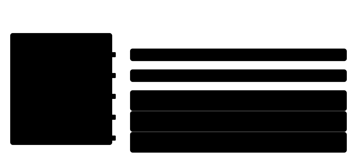
LV-side pinout
The module runs on 3.3 V I²C logic and is 5 V tolerant on the signal lines. All LV pins are fully galvanically isolated from mains.
| Pin | Signal | Function |
|---|---|---|
VCC |
+5 V (4.5..5.5 V) | Module power; 4.5 V minimum for correct operation |
GND |
Ground | Shared with the master — mandatory |
SDA |
I²C SDA | I²C data |
SCL |
I²C SCL | I²C clock |
DRDY |
Data-ready (optional) | Open-drain, LOW pulse ~10 µs every ~100 ms |
Power
VCC parameters
- Nominal voltage: 5 V DC
- Permissible range: 4.5..5.5 V
- Supply current: ~15 mA typical, ~25 mA peak during flash writes
- Ripple: < 50 mV peak-to-peak (for measurement accuracy)
The module carries an on-board regulator, RC filter, ceramic capacitors, and a
ferrite bead — no additional filtering is required from the user.
The module can be powered from the +5V rail of any Arduino board
(UNO, ESP32 DevKitC, etc.).
I²C level compatibility
SDA/SCLoperate at 3.3 V logic (the built-in pull-ups pull the lines to 3.3 V).- The lines are 5 V tolerant: a 5 V master (Arduino UNO / Nano) reads HIGH (~3.3 V) correctly and can drive the bus without a level translator.
- For a bus running entirely at 5 V levels — disable the built-in pull-ups (see below) and add external pull-ups to +5 V on the master side.
Power-on behavior
- Cold start: ~250 ms to the first valid result.
- After a reset (software or brown-out): ~250 ms to recover.
- Until the first valid result, registers read as
0andDATA_VALID= 0.
The library waits for the module to be ready inside dev.begin() —
your code simply calls begin() and continues.
Isolation
The LV side (I²C, power, DRDY) is isolated from the mains terminals.
Treat the mains terminals and the CT-side wiring as live.
- The module's
GNDis not connected to the mains line or neutral. - Do not touch the L/N terminals or the clamp conductor while the circuit is energised.
⚠ Do not open the module enclosure — this voids the factory calibration.
On-board pull-up resistors
Important: every rbAmp module ships with built-in 4.7 kΩ pull-up resistors on SDA and SCL to 3.3 V. For a single module on the bus, external pull-ups are not required — connect the master directly.
When to disable the built-in pull-ups
If the bus has several rbAmp modules (or other I²C devices with their own pull-ups), connecting them in parallel yields too low an effective resistance, which:
- Increases bus consumption
- May exceed the maximum sink current of the I²C master's output stage (typically ≤ 3 mA on 3.3 V logic)
- Adds capacitive load on a long bus while doing little to improve noise immunity
Solution: on the bottom side of the board, near the pull-up resistors, there are
jumper bridges (silkscreen Pull-Up). Cut them with a sharp
blade to disable a pull-up:
- Leave the pull-ups enabled on only one module (or move them to a single point near the master).
- Cut the bridges on the remaining modules.
- If pull-ups are already present on the master board — cut the bridges on all rbAmp modules.
Rule of thumb
| rbAmp modules on bus | Pull-ups |
|---|---|
| 1 | Leave as-is (the built-in 4.7 kΩ works) |
| 2 | Leave on one, cut on the other |
| 3 | Cut on all modules, fit one external 2.7…3.3 kΩ pair near the master |
| 4…6 | Cut on all modules, one external 2.2…2.7 kΩ pair near the master |
| 7…16 | Cut on all modules, one external 1.5…2.2 kΩ pair near the master; check the bus capacitance (≤ 400 pF), lower the bus speed if needed |
The external values are recommended values (calculated from the I²C specification: sink current ≤ 3 mA at 3.3 V, bus capacitance ≤ 400 pF). Connect the external pull-ups to 3.3 V (the logic level of the bus), not to the 5 V VCC supply.
If in doubt: measure the resistance between SDA and VCC with the devices unpowered. It should be in the 1.5..4.7 kΩ range. Lower than that means too many active pull-ups in parallel.

I²C bus parameters
- Default address:
0x50(7-bit) - Address range:
0x08..0x77(reassigned via two-phase address commit, production-OK) - Speed: UNO / Mega / STM32 / RP2040 100 kHz; ESP32 / ESP8266 50 kHz. Do not use 400 kHz.
- Pointer auto-increment: on reads only. A burst-read of
<addr> + N bytesreturns N consecutive bytes starting ataddr. Writes are NOT auto-increment: a burst-write drops bytes 1..N and only the first lands. Multi-byte registers are written byte by byte in separate single-byte transactions. See 09 · API Reference — "Multi-byte writes".
Bus length
I²C is a short bus (~15 cm by default). Many users connect modules with low-quality jumper wires, which pick up a lot of noise and lose many transfers — hence the short limit. Recommended topologies for rbAmp:
| Cable | Max length | Speed |
|---|---|---|
| Standard JST / flat 4-conductor | up to 0.15 m | 100 kHz |
| Twisted pair UTP (cat-5/5e/6) — SDA+GND and SCL+GND in separate pairs | up to 1 m | 100 kHz |
| Twisted pair + I²C buffer (PCA9515 / TCA9617) | up to 3 m | 100 kHz |
| Differential bus (PCA9615 / LTC4332) | up to 100 m | 100 kHz |
For lengths over 0.15 m, twisted pair is mandatory: SDA and SCL must be in different pairs, each with its own ground (for example, blue + blue-white for SDA, green + green-white for SCL). SDA and SCL in a single pair create cross-coupled capacitance that distorts the edges.
⚠ Inside an electrical cabinet, shield the I2C cable. Strong magnetic fields near mains conductors, contactors and transformers induce noise in an unshielded cable. Keep the cable as short as possible and away from the mains wiring.
Mains-side wiring (sensors)
⚠ Mains voltage can kill. Disconnect and lock out the circuit before connecting the L/N terminals or fitting the clamp; have a qualified person do mains wiring and any work inside a panel. Clamp ONE conductor only (L) — never the whole cable (L+N cancel to ~0). Fuse the L tap per local rules.
Voltage sensor (UI* variants)
The board exposes L (line) and N (neutral) terminals. Polarity
matters for the sign of active power:
- Correct (L → L, N → N):
P > 0means consumption (current from the grid into the load),P < 0means export to the grid (generation). - Swapped (L and N reversed): the sign of P inverts — consumption is counted as negative power.
Wire and fuse. A thick wire is not required for the voltage connection: AWG26–22 is enough, because the voltage sensor draws very little current. A fuse in the L line is mandatory, rated up to 0.1 A.
Correct polarity is critical for:
- Correct accounting on the BASIC tier (BASIC counts only
max(P, 0); with swapped polarity the energy counter stays at zero). - Correctly separating consumption and generation on the STANDARD (STD) line.
Quick check: on a purely resistive load (electric kettle, heater, incandescent lamp)
P > 0andPF ≈ 1.0. If P is negative under a consuming load — swap L and N on the board.
Current sensor — SCT-013 CT clamp
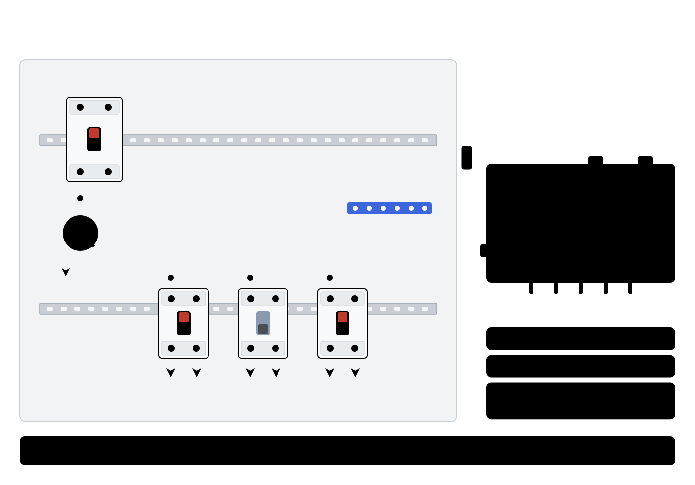
External CT clamps connect to the module through a 3.5 mm jack connector. The connector is keyed — no wiring decisions need to be made.
An arrow on the clamp body shows the current direction for the "normal" orientation. Rules:
- Clamp the CT around the line conductor (L) only going to the load.
- The arrow on the clamp must point in the direction of current toward the load (from the breaker to the load).
- The clamp must close fully — with no gap between the halves of the magnetic core. If the halves do not click fully shut, accuracy is lost.
⚠ Do not run both L and N through a single clamp at once. Their magnetic fluxes are equal and opposite, so they cancel each other out — the sensor will read ~zero even under load.
For more on choosing the SCT-013 model (5A / 10A / 30A / 50A / 100A) and
how to tell the module via dev.setCTModel(code) — see
03_sensor_selection.md.
⚠ CT clamp polarity matters on BASIC: if the clamp arrow points away from the load (or L/N on the terminals are swapped),
P_realreads negative under consumption — and the BASIC tier clampsmax(P, 0), so the Wh counter stays at zero. Flip the clamp on the conductor physically; do not invert it in software.
DATA_READY (DRDY)
An optional pin for polling optimization. If the application polls the
module no more often than once every 100 ms, DRDY can be left unconnected.
Electrical parameters
- Output type: open-drain (no active pull-up to VCC)
- Idle level: HIGH (requires a pull-up on the master side — the MCU's built-in pull-up or an external resistor)
- Ready pulse: LOW for ~10 µs after the RT registers
(
0x86..0xCF) have been updated with fresh data - Pulse frequency: ~10 Hz (one pulse per ~100 ms RT window)
The library can use the line for you: dev.setDrdyPin(pin) attaches it
(internal pull-up, falling-edge interrupt) and dev.waitDataReady() /
dev.readAllReady() wait for the module's next snapshot — see
09 · API reference. Several
modules may share one DRDY line (wired-OR); a line held solid LOW means a
module has a masked event pending (alarm). Without a line the same calls poll.
Semantics
A falling edge on DRDY guarantees that all RT registers are
synchronized and published (the firmware updates them atomically in
an ISR before pulling the pin low). After the falling edge the master can read
0x86..0xCD without risk of getting a split sample.
Use on Arduino
- External interrupt (
attachInterrupton the falling edge) — wakes the master and triggers a read. - Pull-up: either
INPUT_PULLUPon the MCU, or an external 10 kΩ to 3.3 V. On UNO / Nano (AVR) use an external 10 kΩ to 3.3 V — the built-in pull-up (~40 kΩ) is too weak for long DRDY lines.
const int PIN_DRDY = 15;
volatile bool data_ready = false;
#if defined(ESP32) || defined(ESP_PLATFORM)
void IRAM_ATTR on_drdy() { data_ready = true; }   // ESP32 — ISR in IRAM
#else
void on_drdy() { data_ready = true; }             // AVR / STM32duino / RP2040 / SAMD
#endif
void setup() {
    Wire.begin();
    while (!dev.begin()) { delay(500); }
    // Raise the pull-up + attach the ISR AFTER dev.begin() — this
    // guarantees the module is already ready and the pull-up edge will not
    // cause a spurious interrupt before the first RT window is captured.
    // INPUT_PULLUP is fine for most cases; for long
    // lines or AVR hosts add an external 10 kΩ to 3.3 V.
    pinMode(PIN_DRDY, INPUT_PULLUP);
    attachInterrupt(digitalPinToInterrupt(PIN_DRDY), on_drdy, FALLING);
}
void loop() {
    if (!data_ready) return;     // sleep until the next RT window
    data_ready = false;
    float p = dev.readPower(0);
    // ...integration / transmit...
}
DRDY is optional — polling at any rate ≤ 10 Hz works without
it. The library does not depend on DRDY; setDrdyPin() / waitDataReady()
are opt-in helpers.
Connecting to different Arduino hosts
The module works with any Arduino-compatible board through the standard
Wire. Below are the standard default pins for popular variants.
Arduino UNO / Nano (5 V logic)
| rbAmp | Arduino pin |
|---|---|
VCC |
+5V |
GND |
GND |
SDA |
A4 |
SCL |
A5 |
DRDY (opt.) |
any digital, e.g. D2 |
#include <Wire.h>
#include <RbAmp.h>
RbAmp dev(Wire, 0x50);
void setup() {
    Wire.begin();          // SDA=A4, SCL=A5 by default
    Wire.setClock(100000); // 100 kHz — no 50 kHz clamp needed on AVR
    while (!dev.begin()) { delay(500); }
}
The UNO is a 5 V host, no level translator needed (the module's SDA/SCL lines are 5 V tolerant). The module's built-in pull-ups pull the lines to 3.3 V, which a 5 V master reads as HIGH correctly.
Arduino Mega 2560 (5 V logic)
| rbAmp | Mega pin |
|---|---|
VCC |
+5V |
GND |
GND |
SDA |
D20 |
SCL |
D21 |
DRDY (opt.) |
any digital, e.g. D18 (supports interrupts) |
Identical to the UNO in code, only the physical pins differ. No level translator needed.
ESP32 / ESP32-S3 / ESP32-C3 (3.3 V logic)
| rbAmp | ESP32 DevKitC pin |
|---|---|
VCC |
+5V (powered from USB-5V on the DevKitC) |
GND |
GND |
SDA |
GPIO21 |
SCL |
GPIO22 |
DRDY (opt.) |
any free GPIO, e.g. GPIO4 |
#include <Wire.h>
#include <RbAmp.h>
RbAmp dev(Wire, 0x50);
void setup() {
    Wire.begin(21, 22);    // SDA=21, SCL=22 (or Wire.begin() with board defaults)
    Wire.setClock(50000);  // ESP32: 50 kHz
    while (!dev.begin()) { delay(500); }
}
The ESP32 is a 3.3 V host, direct connection to the module. VCC power is taken from the DevKitC's +5V pin (which is connected to USB-5V directly).
ESP32 50 kHz clamp — the recommended pattern. Instead of an explicit
Wire.setClock(50000)call, define the opt-in macro before the include —begin()will apply the clamp internally:```cpp
define RBAMP_ESP32_CLAMP_HZ 50000
include
```
The macro is opt-in (not default-on) — so that explicit user calls to
Wire.setClock()(for example when an OLED shares the bus) are preserved. Both forms work — pick the one that reads better in your sketch.If your ESP32 board does not break out a 5 V pin (some compact ESP32-S3 / C3 modules get by with only Vin or no 5 V at all) — power rbAmp from an external 5 V source (for example, a USB charger + breakout), with GND shared with the ESP32.
A separate note on resetting the module:
For a software reset of the module, use
dev.reset()— the library sends the command and the module reboots in ~100 ms. If you need a hard reset (for example, to recover from a brick state) — power-cycle VCC (disconnect for 1+ second).
ESP8266 (Wemos D1 mini / NodeMCU, 3.3 V logic)
| rbAmp | ESP8266 pin (NodeMCU) |
|---|---|
VCC |
Vin or +5V |
GND |
GND |
SDA |
D2 (GPIO4) |
SCL |
D1 (GPIO5) |
DRDY (opt.) |
D5 (GPIO14) |
#include <Wire.h>
#include <RbAmp.h>
RbAmp dev(Wire, 0x50);
void setup() {
    Wire.begin(D2, D1);      // SDA=GPIO4, SCL=GPIO5
    Wire.setClock(50000);    // ESP8266 software I²C: 50 kHz for consistency with ESP32
    while (!dev.begin()) { delay(500); }
}
The ESP8266 is a 3.3 V host, direct connection.
STM32duino (STM32F1 dev-board F103 / Black Pill F411, 3.3 V logic)
| rbAmp | STM32 pin (STM32F1 dev-board) |
|---|---|
VCC |
+5V |
GND |
GND |
SDA |
PB7 (I²C1_SDA) |
SCL |
PB6 (I²C1_SCL) |
DRDY (opt.) |
any GPIO with EXTI, e.g. PA0 |
#include <Wire.h>
#include <RbAmp.h>
RbAmp dev(Wire, 0x50);
void setup() {
    Wire.begin();           // SDA=PB7, SCL=PB6 by default for I²C1
    Wire.setClock(100000);  // the STM32 HAL I²C needs no 50 kHz clamp
    while (!dev.begin()) { delay(500); }
}
STM32duino supports multiple Wire instances (Wire1,
Wire2 for a second I²C). If the primary bus is busy — use the
second I²C peripheral.
RP2040 / SAMD (Raspberry Pi Pico, arduino-pico)
| rbAmp | RP2040 pin (Pico) |
|---|---|
VCC |
VBUS (5 V from USB) or +5V |
GND |
GND |
SDA |
GP4 |
SCL |
GP5 |
DRDY (opt.) |
any GP |
#include <Wire.h>
#include <RbAmp.h>
RbAmp dev(Wire, 0x50);
void setup() {
    Wire.setSDA(4);
    Wire.setSCL(5);
    Wire.begin();
    Wire.setClock(100000);  // the RP2040 hardware I²C needs no 50 kHz clamp
    while (!dev.begin()) { delay(500); }
}
The RP2040 is a 3.3 V host, direct connection. On SAMD boards (Arduino Zero,
MKR) Wire.begin() with defaults works the same way — the specific pins
depend on the board.
Pico via VSYS (battery / external power): the
VBUSpin is present only when powered over USB. If the Pico runs from a battery or an external source throughVSYS—VBUSwill carry nothing. Feed 5 V from an external source to the module'sVCCdirectly, with GND shared with the Pico.
Reference wiring diagram (ESP32 + single module)
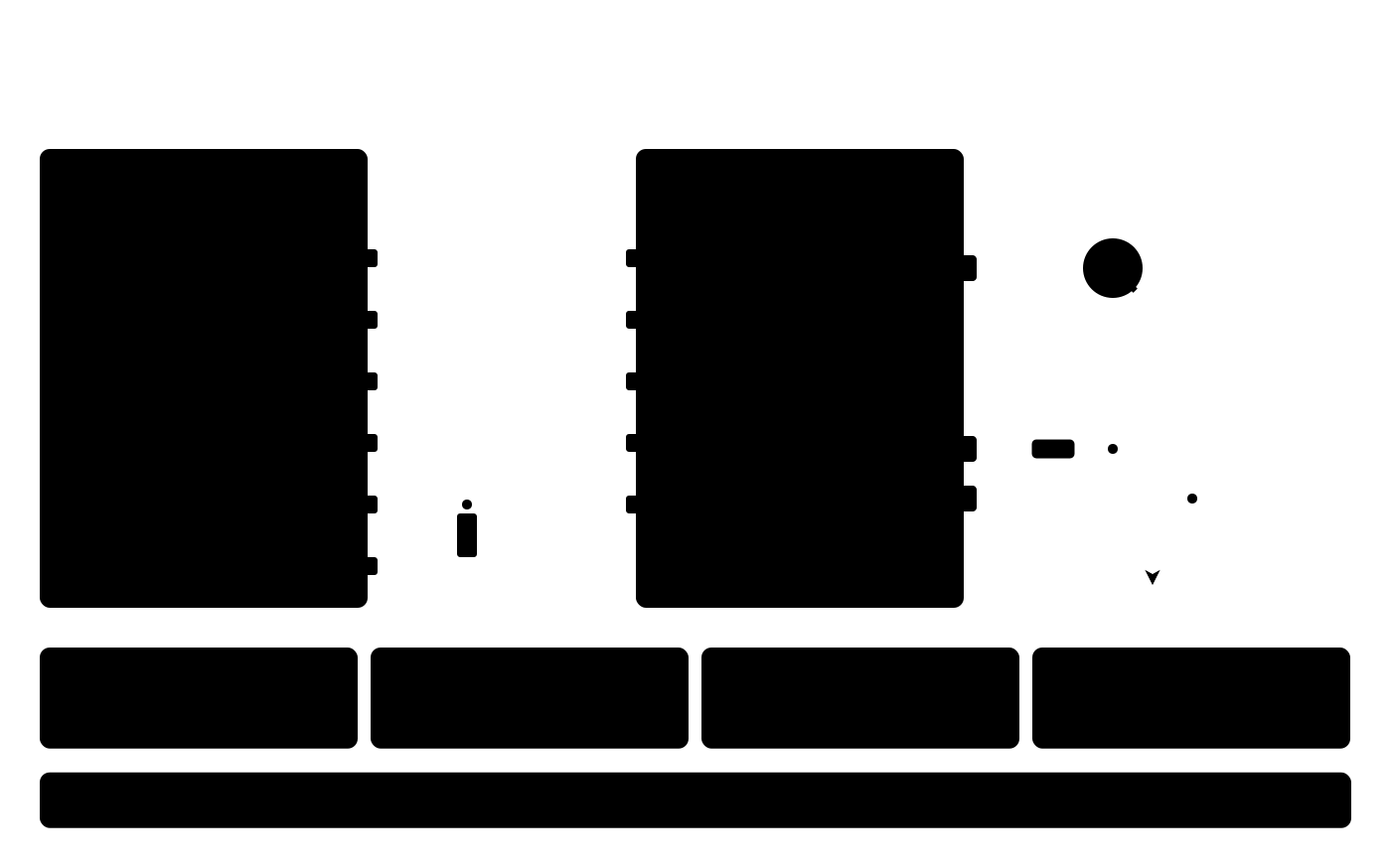
In this configuration:
- External pull-ups on I²C are NOT needed (built into the module).
- DRDY is optional; as in the picture, use an external 10 kΩ pull-up to 3.3 V (INPUT_PULLUP on the ESP32 pin also works on short wires).
- The SCT-013 jack is fully inserted.
- The clamp is fully closed on the L wire, arrow toward the load.
Reference wiring diagram (Arduino UNO + single module)
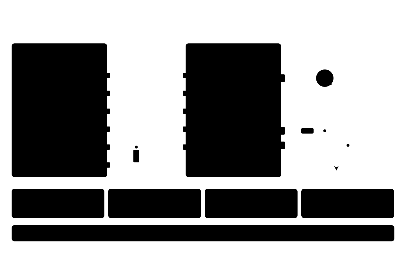
In this configuration:
- External pull-ups on I²C are NOT needed.
- The UNO is 5 V logic; the module's SDA/SCL are 5 V tolerant, no level translator required.
- DRDY has a 3.3 V level — on the UNO a TTL input reads this as HIGH (VIH_TTL ≥ 2.0 V, 3.3 V > 2.0 V). A DRDY pull-up is recommended specifically to 3.3 V for safety: if the DRDY pin's internal protection circuits are not 5 V tolerant (separately from the I²C lines, whose 5 V tolerance is confirmed), a pull-up to 5 V would create a small leakage current through the ESD diodes into the module's 3.3 V rail. To 3.3 V — never a problem.
Multi-phase models and the STANDARD (STD) line
Multi-channel and multi-phase SKUs keep the same LV pinout (VCC / GND / SDA / SCL / DRDY). Only the mains side changes — more L terminals and more CT jack connectors.
STANDARD (STD) modules use the same I²C wiring as BASIC modules — same
four signal lines, same pull-up and bus rules as above. Nothing changes in the
connection; dev.begin() detects which line is attached (dev.line()), and
the same sketch serves both. Notes:
- Calls that exist only on the STD line (the
std*family, reactive and apparent power) returnRB_ERR_NOT_IMPLEMENTEDon a BASIC module (on BASIC, reactive power is not exposed by this library). - Some STD features depend on the module image version: micro-resolution
energy counters, the starting current for energy, voltage phase angles and
the phase sequence need an image of at least
0x0001007B(dev.stdReadImageVersion()). On an older image they are reported as "not available". - The number of voltage and current channels comes from the module
(
dev.stdInfo()); the library exposes up toRBAMP_MAX_CHANNELS(7) current channels.
Multi-module bus — the primary topology
The library's canonical use case is several
rbAmp modules on one I²C bus, managed by a single Arduino /
ESP32 through RbAmpFleet. All the rules and optimizations below are designed
for exactly this topology; a single module is a special case (the same
handle, but the fleet calls degenerate into trivial ones).

Typical deployments
| Scenario | Configuration | Module count |
|---|---|---|
| 80% canon: home feed + submeters | 1× UI1 (feed, mains-energy) + 3-6× UI1/I1 (loads) | 4-7 |
| Sub-panel with current breakdown | 1× UI1 (feed) + 1-2× I2/I3 (per-circuit current) | 3-5 |
| Industrial sub-metering | 1× UI1 (feed) + N× I2/I3 (per machine, current breakdown) | up to ~16 |
Electrical limits
- Module count: up to ~16 (total bus capacitance ≤ 400 pF at 100 kHz; at 50 kHz there is more margin).
- Pull-ups for the fleet bus (important): each module ships with built-in 4.7 kΩ. On a multi-module bus N pull-ups work in parallel → the sink is overloaded and the bus cannot pull down to LOW. Cut the built-in pull-ups on all modules except one (or cut them on all and keep only external pull-ups (2.7…3.3 kΩ for 3 modules, lower for larger buses — see the table above) to 3.3 V at a single point on the bus — recommended for long runs / noise / ESP32 as master).
- The ESP32's internal pull-ups (~45 kΩ) are too weak for a multi-module bus with real run lengths — external pull-ups are needed (values: see the table above). This is part of the three-layer mitigation against bus-hang on a marginal bus — see 10 · Troubleshooting, the section "ESP32 project hangs".
Addressing — provisioning and field-swap (production-OK)
The default factory address is 0x50. Every new or replacement module
goes through provisioning (once): reassignment from 0x50 to a
working address + optional saving of the configuration (CT models,
group_id, label) to flash. Factory-mode is not required —
the address change works directly in production via two-phase address commit.
Method 1 — RbAmpFleet::provision() (recommended)
RbAmp* dev = nullptr;
if (RbAmpFleet::provision(Wire, /*desired=*/0x52, /*save=*/true, dev)) {
    fleet.add(dev);   // ready handle, now in the fleet
}
A single call scans 0x50, performs the two-phase address commit, resets,
searches for the module at the new address in the boot window, and (optionally)
issues SAVE_USER_CONFIG for persistence. Returns false on a discipline
violation (see below) or a transport failure.
Method 2 — low-level prepare/commitAddressChange (manual form)
dev.prepareAddressChange(0x52);   // candidate in RAM
dev.commitAddressChange();        // arms 0xA5 + COMMIT_ADDR + reset
delay(300);                        // boot window
The same two-phase mechanism as in provision(), without the fleet wrapper.
Used when RbAmpFleet has not been created.
Wire protocol under the hood (for reference)
1. write candidate_addr → REG_I2C_ADDRESS (0x30, in RAM)
2. write 0xA5 → REG_ADDR_COMMIT_MAGIC (0x31, armed)
3. issue CMD_COMMIT_ADDR (opcode 0x30 in REG_COMMAND)
4. wait ~700 ms (flash erase + write)
5. issue CMD_RESET (opcode 0x01) — CMD_COMMIT_ADDR does not auto-reset
6. wait ~300 ms; the module responds at the new address
✅
REG_I2C_ADDRESS (0x30)reads the active address on boot (v1.3 addr-boot-sync). After the post-commit reboot, reading0x30shows the new active address. The staging-echo behavior persists untilCMD_COMMIT_ADDR+ reset.⚠ Provisioning discipline — MUST one virgin at a time.
The most common source of provisioning failures is having more than one module with the factory address
0x50on the bus. It is physically impossible to distinguish them over I²C (open-drain bus: both modules will ACK identically, and the read-back data will be "stuck together").So the rule is strict (a normative MUST, not a recommendation): at the moment you call
RbAmpFleet::provision()(orprepareAddressChange()), there must be exactly one module at0x50(a new one or one returned to factory defaults via a separate bench tool). No "I'm sure these two modules are different — I'll just separate them now" — it will not work; the collision shows up later, once you already think the fleet is clean.Recovery path if you suspect a discipline violation: 1. Power-cycle all modules. 2. Physically disconnect all but one "virgin" module. 3. Call
RbAmpFleet::provision()on the single-module bus. 4. Add the remaining modules one at a time, provisioning each separately.
Bus power budget
At 50 kHz, one read transaction ≈ 200-400 µs. A full RT block of one channel (U + I + P + PF) ≈ 5-8 ms per channel.
| Configuration | Bus per cycle | At 50 kHz | Max polling rate |
|---|---|---|---|
| 1× UI1, RT block | ~5 ms | < 5 ms | 100+ Hz (but the module updates at 10 Hz) |
| 1× UI3, RT block + period | ~25 ms | ~25 ms | up to 10 Hz |
| 5× UI1, RT block | ~25 ms | ~25 ms | up to 10 Hz |
| 16× UI3, RT + period | ~400 ms | 400 ms > 100 ms | can't keep up with the module (10 Hz); ~2 Hz at best |
The numbers are estimates (200-400 µs/transaction depends on the MCU). The numbers are estimates and depend on the host MCU.
Rule: at 50 kHz the comfortable limits are 8-10× UI3 or 15-16× UI1 at 5 Hz polling (every second module window), and roughly half of that at the full 10 Hz.
Period sync

For tariff metering, all modules must take their snapshot over the same interval. Two strategies:
Strategy 1 — sequential snapshot + common settle (any firmware):
RbAmp meters[N];   // array of initialized modules
void period_cycle() {
    // Phase 1: sequential snapshot
    for (auto& m : meters) m.latchPeriod();
    // Phase 2: common settle (≥ 50 ms)
    delay(50);
    // Phase 3: read the snapshots with skip_latch=true
    for (auto& m : meters) {
        RbAmpSnapshot snap;
        m.readPeriodSnapshot(snap, /*skip_latch=*/true);
    }
}
Skew between modules: 16 modules × ~1 ms/snapshot = ~16 ms across a 60-s period. Negligible for energy totals.
Strategy 2 — General-Call broadcast snapshot (requires enable):
All modules take their snapshot with a single I²C frame on addr 0x00:
addr=0x00 | A5 27 <group> <tick_lo> <tick_hi> (5 bytes)Skew = 0 (atomic). Pre-config (once on each module of the fleet):
- Set
REG_FLEET_CONFIG.bit0 = 1viaCMD_SAVE_USER_CONFIG. CMD_RESET— GC reception is activated on boot.- After reset, the master sends the 5-byte frame on
0x00. - Witness: for each expected module, read
REG_V03_PERIOD_VALID (0x07).!=1→ fall back to strategy 1.
Which to use: - < 8 modules: strategy 1 (simpler, no enable required). - ≥ 8 modules or tight synchronization: strategy 2.
GC group filtering (multi-tenant bus)
REG_GROUP_ID (0x28) lets you have several GC domains on one bus:
group = 0x00→ all-call (all modules with GC enabled take a snapshot).group = N→ only modules withREG_GROUP_ID = Ntake a snapshot.
Use case — separating tariff groups (day vs night) on one shared bus.
Failure modes
| Symptom | Cause | What to do |
|---|---|---|
i2c bus scan shows several modules at one address after a field add |
A new module at 0x50 conflicts with an already-addressed one |
Re-address the new module separately before adding it |
| One module NACKs more often than the others | Cable fault / VCC drop | Check VCC under load |
| One module's Wh consistently diverges | The module's own clock differs from the master's | Energy is integrated on the master clock; compare with master_dt_ms, not latch_ms |
| After a GC frame, one module does not take a snapshot | FLEET_CONFIG.bit0 = 0 or group mismatch |
Check REG_FLEET_CONFIG and REG_GROUP_ID |
Bus design notes
- Clock stretching: the module's snapshot pauses it only for microseconds; SCL is not stretched significantly. For the Raspberry Pi BCM283x (known hw bug in stretching): the standard precaution is 50 kHz + retry.
- Length with >4 modules: consider an I²C buffer (PCA9515) at ≥ 8 modules + length > 1 m.
Detailed multi-module scenarios — in 06 · Examples.
What's next
- 02 · Module Tiers — firmware behavior by tier
- 03 · Current Sensor Selection — which SCT-013 model and how to tell the module
- 05 · Quickstart — your first working sketch
- 10 · Troubleshooting — what to do if the bus is not working / I_rms is unstable / the sign of P is wrong
Source & issues: rb-amp/rbamp-arduino · this page in the repo: docs/04_hardware.md (v1.6.2)