Your meter gives one number. See which circuit makes the bill.
Start with one rbAmp module on your own controller, and grow to a whole-panel system without replacing what you bought. Each module measures voltage, current, power and energy on individual circuits.
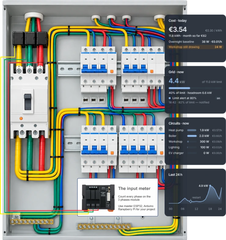
What do you want to know?
Per-circuit monitoring
See what each circuit and appliance uses, not just the whole house.
"One number from the meter is not enough."
Solar and battery
Separate grid import, self-consumption and export.
"Export breaks my charts; the counter jumps after a reboot."
Standby consumption
Find the baseline that never switches off.
"Everything is off and the meter still turns."
Sub-metering
One meter per room, load or tenant on one device.
"A meter per tenant, not a cabinet of meters."
Industrial integration
Hand readings to an inverter, PLC or SCADA over Modbus RTU (external RS-485 transceiver).
"My inverter expects a meter on RS-485."
Whole-panel synchronized
Every channel measured at the same instant.
"All meters of the site at one instant."
Measure it. Meter it. Connect it.
Start with one module. Add a meter, then a hub. Nothing you bought is replaced. Available today: Measure · Meter. Next: Connect — a ready-made RBgrid hub.
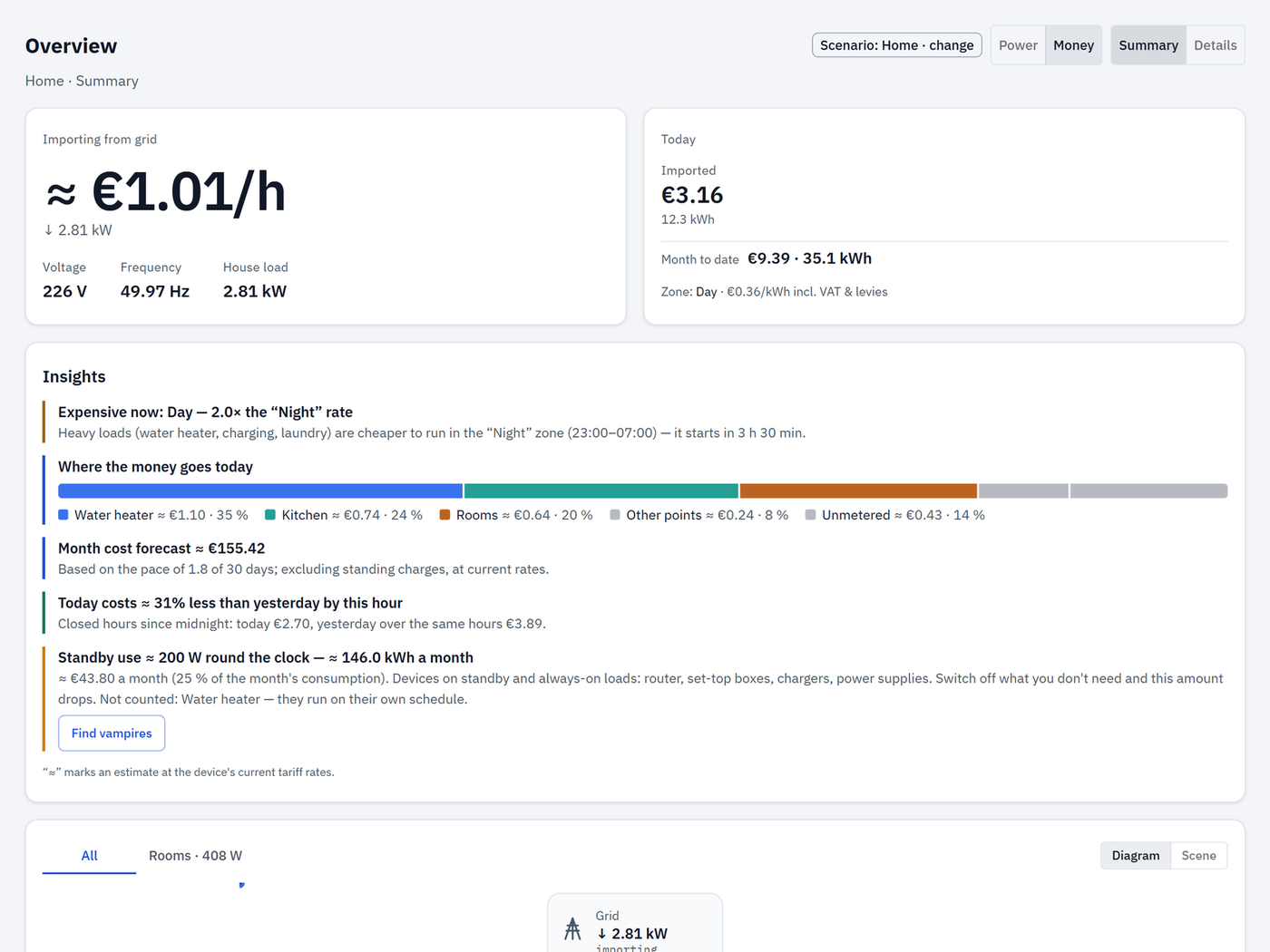
RBgrid: see your electricity as money
Put an ESP32 hub next to your rbAmp modules and RBgrid shows what every measured circuit costs — right now, today and this month — on your own tariff zones. It runs on the hub: no account, no cloud, no subscription. If you run Home Assistant, it stays as it is: the hub plugs into it over MQTT.
The hub firmware is source-available, free for personal and non-commercial use.
Latest from RBgrid

STD: data you can trust
Metering lives on the device, not in your software: the counters are kept and saved on the module, so a restart of your controller loses nothing.
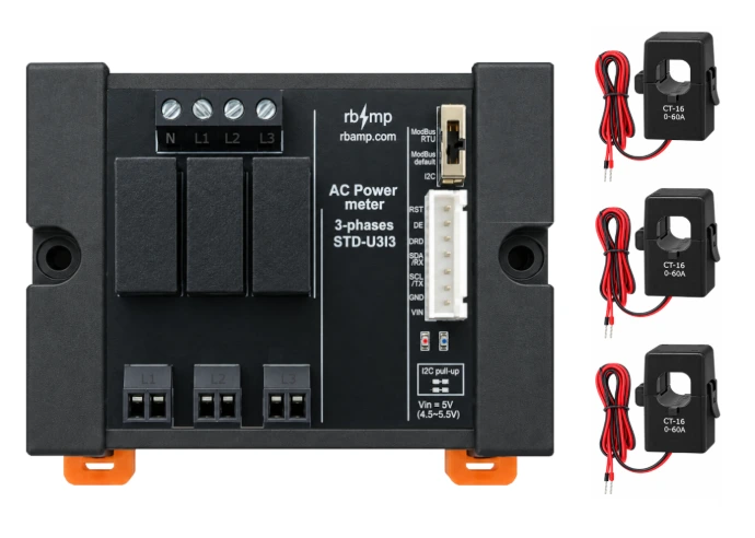
STD: data you can trust
Metering lives on the device, not in your software. Source: Docs › STD › Energy and periods
Counters on the device
Counters on the device, saved every second.
Import and export
Import and export: two counters, not a balance.
Small loads don't hide
Current in microamperes, energy in microwatt-hours.
Updates that roll back
Signed image; metering continues during the update.
Safe by design, stated per model. The side you connect to your controller is low-voltage and isolated from the mains measurement inputs; current is measured through a clamp; the exact wording per line is on the safety page.
Factory calibrated. Every module ships calibrated; accuracy is stated per sensor rating in the documentation — as system accuracy, module plus sensor, not as one number. Sensor ratings
Your first project
BASIC SCT-UI3 — your first measured circuit. What else you need:
- an SCT-013 clamp sensor
- an ESP32 board
- a 5 V supply
- four bus wires (I²C)
- the library for your stack
Works with the tools you already use
ESPHome · ESP-IDF · Arduino · Python · Modbus RTU. Quick starts: ESPHome · ESP-IDF · Arduino · Python · STD over Modbus RTU
ESPHome — BASIC SCT-UI1 + SCT-013 · ESP32 · I²C
rbamp:
  id: meter1
  address: 0x50
  ct_model: SCT_013_030

sensor:
  - platform: rbamp
    rbamp_id: meter1
    voltage:
      name: "Mains Voltage"
    current:
      name: "Mains Current"
    power:
      name: "Mains Power"
    energy:
      name: "Mains Energy"
Source: rbamp-esphome README · Quick start · Full example →
ESP-IDF — BASIC SCT-UI1 + SCT-013 · ESP32 · I²C
rbamp_handle_t dev;
ESP_ERROR_CHECK(rbamp_new(bus, 0x50, &dev));
ESP_ERROR_CHECK(rbamp_begin(dev));
ESP_ERROR_CHECK(rbamp_set_sensor_class(dev,
                RBAMP_SENSOR_SCT013));
ESP_ERROR_CHECK(rbamp_set_ct_model(dev, 3));

rbamp_snapshot_t s;
if (rbamp_read_all(dev, &s) == ESP_OK) {
    ESP_LOGI("app", "P=%.1f W", (double)s.power[0]);
}
Source: rbamp-esp-idf README · Quick start · Full example →
Arduino — BASIC SCT-UI1 + SCT-013 · ESP32 · I²C
#include <Wire.h>
#include <RbAmp.h>

RbAmp dev(Wire, 0x50);

dev.setSensorClass(RbAmpSensorClass::Sct013);
dev.setCTModel(RbAmpCTModel::Sct013_030);

RbAmpPeriodSnapshot snap;
if (dev.readPeriodSnapshot(snap)) {
    Serial.println(snap.avg_p[0]);
}
Source: rbamp-arduino README · Quick start · Full example →
Python — BASIC SCT-UI1 + SCT-013 · Raspberry Pi · I²C
from smbus2 import SMBus
from rbamp import RbAmp, RbAmpSensorClass

with SMBus(1) as bus:
    with RbAmp(bus, 0x50) as dev:
        dev.set_sensor_class(RbAmpSensorClass.SCT_013)
        dev.set_ct_model(3)
        print(f"P[0] = {dev.power[0]:.2f} W")
Source: rbamp-python README · Quick start · Full example →
STD over Modbus RTU — switch: Modbus default (9600 8N1, unit 1) · UART TTL, RS-485 through an external transceiver
# float32 profile: total P (float)
mbpoll -m rtu -b 9600 -P none -a 1 -0 -1 -o 2 \
  -t 3:float -B -r 52 -c 1 <port>

# float32 profile: frequency, import kWh, export kWh (float)
mbpoll -m rtu -b 9600 -P none -a 1 -0 -1 -o 2 \
  -t 3:float -B -r 70 -c 3 <port>
Source: STD docs · Examples · Full example →
What stays the same as you grow
Whatever you add — a module, a meter, a hub — the bus, the library, the contract and the moment of measurement stay the same.
One bus
Two wires from one circuit to a whole panel; up to about 16 modules per bus, limited by bus capacitance.
One library
begin() detects the line and the channel count.
One contract
Published, versioned register maps.
One snapshot
The whole site frozen at one instant over the bus.
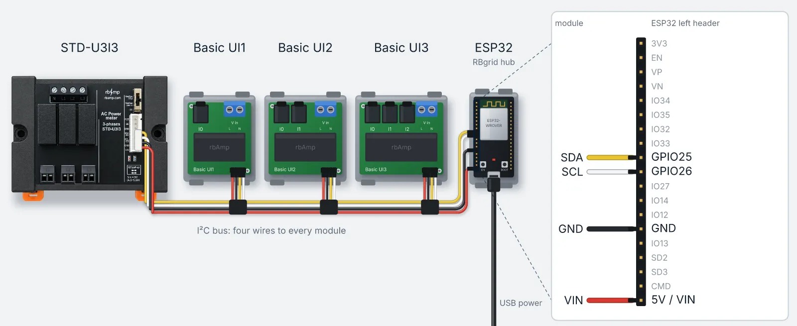
One installation that grows
Every step adds; nothing is replaced.
1 · Modules and your master
BASIC or STD on your own controller.
2 · BASIC and STD on one bus
STD also standalone over Modbus RTU.
Platform releases
New modules, libraries and firmware — only when something ships, at most once a month.