04 · Wiring
This chapter covers physically wiring rbAmp to an ESP32: GPIO selection, pull-up rules, the multi-module bus, power, the optional DRDY line, and address provisioning.
Canonical deployment — a multi-module fleet on a single bus. 80% of field installations consist of 1× UI1 (mains) + N× I2/I3 (sub-meters) on one ESP32 I²C bus, with the pull-ups set per the table below. See 01_overview.md for the fleet picture. A single module is the minimal case, not the canon. This chapter covers both topologies, but multi-module is flagged as the "primary topology" in the relevant sections.
STANDARD (STD) modules. Wiring, pull-up rules, power and the optional DRDY line are the same for BASIC and STANDARD modules, and the same YAML works for both — the component identifies the connected module at boot.
new_address:works on both module lines. General-call fleet sync (fleet_gc_enable:/group_id:) applies to BASIC modules only; on a STANDARD module those keys are ignored with a log line.DANGER: the L/N terminals carry mains voltage. De-energise and lock out the circuit before connecting, have a qualified person do mains wiring and any work inside a panel, clamp ONE conductor only (L), and never leave the CT clamp on a conductor with the CT jack unplugged.
Wire and fuse. A thick wire is not required for the voltage connection: AWG26–22 is enough, because the voltage sensor draws very little current. A fuse in the L line is mandatory, rated up to 0.1 A.
Mains side in one glance. Mains L and N go to the module's two terminals (they provide the voltage reading); the CT clamp plugs into the CT jack and goes around the L conductor only, arrow toward the load. Everything else in this chapter is the low-voltage side.
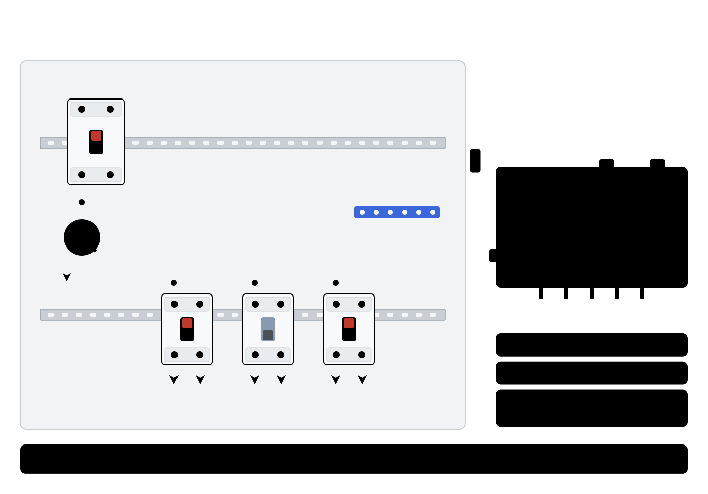
LV-side pinout
The low-voltage side of the module exposes five signals. All are galvanically isolated from the mains — the GND pin is the ESP32 GND, not the mains neutral.
| Pin | Signal | Description |
|---|---|---|
VCC |
+4.5..+5.5 V DC | Module power. 5 V nominal; below 4.5 V the readings may become unreliable. |
GND |
Common | Common with the master. Required. |
SDA |
I²C data | 3.3 V logic; 5 V-tolerant. |
SCL |
I²C clock | 3.3 V logic; 5 V-tolerant. |
DRDY |
Data ready (optional) | Open-drain output. ~10 µs LOW pulse every ~100 ms after the instantaneous registers update. |
GPIO selection on the ESP32
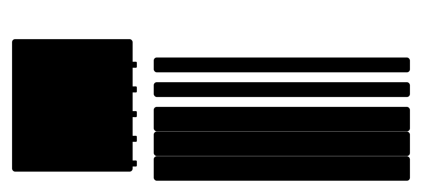
Any pair of GPIOs that support I²C will work. The ESP32 peripheral matrix lets you route I²C to almost any pin. Practical constraints:
- GPIO0 and GPIO2 are boot-strapping pins. A low level on them at power-on blocks the boot. Do not use.
- GPIO 6..11 are wired to the onboard flash or PSRAM on most ESP32-WROOM modules. Unavailable.
- GPIO 34..39 are input-only. Not suitable for I²C (which needs bidirectional drive).
- Do not connect any ESP32 GPIO to a module reset line — the module is reset with an I²C command, and no hardware reset pins are needed on the master side.
Recommended default assignments that work on most ESP32-DevKitC boards:
| Signal | GPIO | Note |
|---|---|---|
| SDA | GPIO21 | Default in all example YAML |
| SCL | GPIO22 | Default in all example YAML |
| DRDY | GPIO15 | Optional; any input-capable pin works |
If GPIO21/22 are taken, pick any other valid pair and update the i2c: block in the YAML.
Wiring a single module
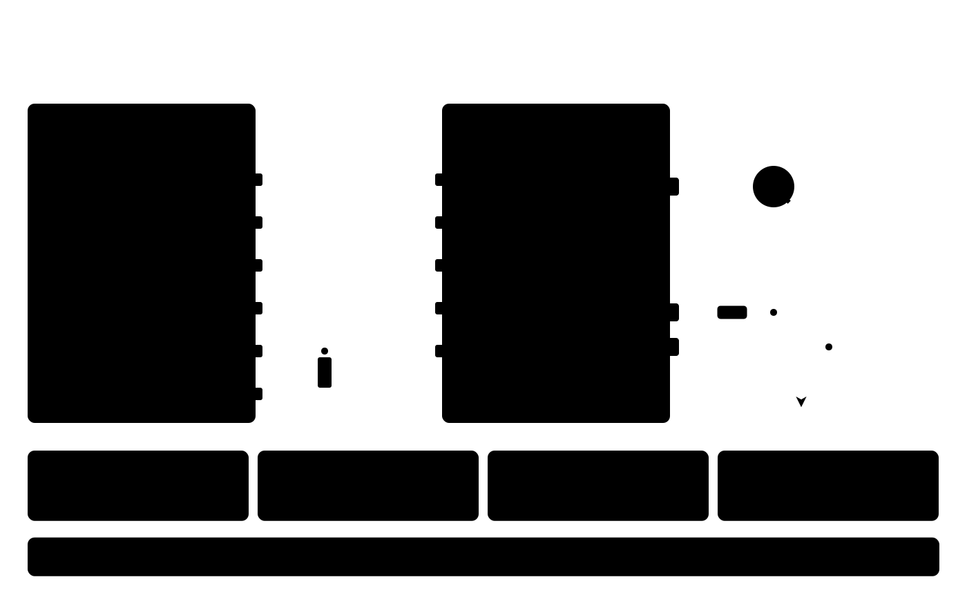
The complete ESP32 wiring is shown in the reference schematic below.
External pull-up resistors are not needed for a single module — the rbAmp board already has built-in 4.7 kΩ pull-ups on SDA and SCL to 3.3 V.
Multi-module bus (primary topology)
Most rbAmp deployments are a fleet of several modules on a single ESP32 I²C bus: one UI1 on mains plus several I2/I3 on sub-branches. This is the primary topology the component was designed for, and the pull-up configuration below is optimized for it.

When two or more modules (or other I²C devices with their own pull-ups) share one bus, their pull-ups add in parallel. The combined resistance drops below the effective minimum — which leads to:
- Excessive bus consumption.
- Possible overload of the ESP32 open-drain outputs (typically ≤ 3 mA at 3.3 V).
- Higher capacitive load on a long bus.
The bottom side of each rbAmp PCB has solder jumpers labeled Pull-Up. Cutting the trace with a sharp blade disconnects that module's built-in 4.7 kΩ pair.
| Modules on the bus | Pull-up configuration | Effective R |
|---|---|---|
| 1 | Leave the built-in pair. No external needed. | ~4.7 kΩ |
| 2 | Leave only on the first; cut the second. | ~4.7 kΩ |
| 3 | Cut on all. One external pair of 2.7..3.3 kΩ at the ESP32. | 2.7..3.3 kΩ |
| 4..6 | Cut on all. One external pair of 2.2..2.7 kΩ at the ESP32. | 2.2..2.7 kΩ |
| 7..16 | Cut on all. One external pair of 1.5..2.2 kΩ at the ESP32 + a bus-capacitance check (see below). | 1.5..2.2 kΩ |
| ESP32 already provides pull-ups | Cut on all modules. The ESP32 internal pull-ups (≥50 kΩ) are weak — a long bus still needs external 2.2..4.7 kΩ. | as above |
The external values are recommended values (calculated from the I²C specification: sink current ≤ 3 mA at 3.3 V, bus capacitance ≤ 400 pF). Connect the external pull-ups to 3.3 V (the logic level of the bus), not to the 5 V VCC supply.

Selection logic: the effective R_pullup is the parallel combination of all active pull-ups. The target range is 1.5..4.7 kΩ (the minimum is bounded by the ESP32 sink current ≤ 3 mA at 3.3 V; the maximum by the bus RC time constant). Formula: 1/R_eff = N/R_unit. For the built-in 4.7 kΩ pair: 2 modules = 2.35 kΩ, 3 = 1.57 kΩ, 4 = 1.18 kΩ — at 3 modules it already gets too low, which is why the table zeroes out the built-in jumpers starting at 3 modules and switches to a single external pair.
Diagnostic check: measure the resistance between SDA and VCC with the power off. The result should be in the 1.5..4.7 kΩ range. Below 1.0 kΩ means too many active pull-ups in parallel; above 10 kΩ means no active pull-up (check the jumpers).
Bus capacitance (for ≥7 modules or total wiring length > 50 cm): the I²C spec limits the total C_b to ≤ 400 pF. A short bus with 2-3 modules is typically 50..100 pF; a 1 m bus with 10 modules can climb to 300..400 pF. When you are close to the limit, drop to frequency: 50kHz (if still on 100 kHz) or use an active-pullup IC (for example the PCA9517).
Bus speed
Set frequency: 50kHz in the ESPHome i2c: block. On the current firmware this is mandatory for reliable operation with ESP-IDF v5:
i2c:
  sda: GPIO21
  scl: GPIO22
  frequency: 50kHz    # recommended on ESP32 — ESP-IDF i2c_master driver interaction, see below
The module periodically NACKs reads from an ESP32 at 100 kHz (a noticeable share of transactions) because of the interaction between the ESP-IDF v5 i2c_master driver timing and the post-STOP recovery window of the module's I²C peripheral. At 50 kHz NACKs are much rarer, and the per-byte retry inside the component recovers > 99% of valid reads.
Firmware has hardened the module's I²C recovery window (shipped in v1.1 and v1.3), which shrank the module-side contribution — but 50 kHz remains the recommended setting on ESP-IDF-based masters because the driver-timing interaction persists at 100 kHz. Treat it as the standing recommendation for ESP32, not a temporary workaround awaiting a fix.
Other I²C masters run this module at 100 kHz cleanly: STM32 HAL, RP2040 SDK, Raspberry Pi smbus2 (Linux-kernel I²C), and non-ESP32 Arduino (AVR / STM32duino). Note the axis is the driver, not the board: Arduino on an ESP32 uses the same ESP-IDF i2c_master driver, so it wants 50 kHz too — only non-ESP32 Arduino runs 100 kHz.
Reference schematic — one ESP32 + one rbAmp
Notes:
- The 10 kΩ resistor on DRDY sits on the master side (near the GPIO), not on the module side. DRDY is open-drain, with no internal pull-up.
- The CT-jack must be fully inserted; the clamp fully encloses a single conductor with its arrow pointing toward the load.
- The L/N polarity at the terminals affects the sign of P (see 03_sensor_selection.md).
Power
Module power (VCC)
The module requires +4.5..+5.5 V DC. Current consumption:
| Mode | Typical |
|---|---|
| Steady-state measurement | ~15 mA |
Flash write (during ct_model: / address provisioning) |
~25 mA peak, ~700 ms |
| Boot warm-up (~250 ms) | ~15 mA |
The 5V pin on an ESP32-DevKitC (usually tied to the USB VBUS) can power the module directly — the USB host must supply the combined ESP32 current (~200 mA) + rbAmp (~15 mA peak) = ~215 mA. For installations where the ESP32 is powered from an external 5 V SMPS, connect VCC to the same 5 V rail.
ESP32 brownout
The ESP32 brownout detector trips at ~2.43 V on VDD. When it trips, the I²C bus goes idle while the module keeps measuring autonomously (it has its own 5 V supply). When the ESP32 recovers, setup() restores the accumulated energy from NVS before the first update(). Home Assistant sees neither a gap nor a reset in the energy graph.
Optional DRDY
The module's DRDY pin is open-drain. It pulses LOW for ~10 µs every ~100 ms right after the block of instantaneous registers updates. It does not fire on the period snapshot.
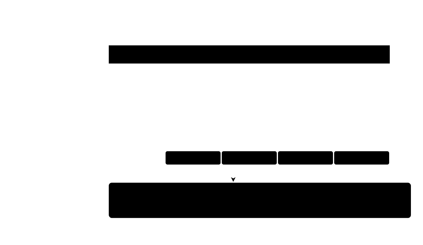
At update_interval: 60s you can omit DRDY — the component checks the status register at the start of each update() and skips the read if the module is not ready. The component logs the DRDY pin; reads are timer-driven (update_interval).
DRDY wiring
DRDY is open-drain: it pulls LOW but cannot drive HIGH. It needs an external pull-up:
rbAmp DRDY  ──────────────────┬── ESP32 GPIO (input)
                                 |
                               [10K]
                                 |
                               3.3V
10 kΩ to 3.3 V. Do not connect DRDY to 5 V, even though SDA/SCL are 5 V-tolerant — DRDY is a separate signal, and the absolute maximum on an ESP32 input GPIO is 3.6 V.
Declare the pin in the YAML:
rbamp:
  id: meter1
  drdy_pin: GPIO15
Multi-module DRDY
The DRDY signals from several modules can be wire-OR'd onto a single ESP32 GPIO (open-drain outputs combine naturally). The shared signal goes LOW when any module has updated its instantaneous registers. The component only logs the pin; it does not tell which module fired.
If you need separate signals, route each module's DRDY to its own GPIO and declare drdy_pin: in each rbamp: block individually.
Address provisioning on a multi-module bus
All rbAmp modules ship from the factory at address 0x50. Before connecting
several modules to one bus, each needs a unique address. On v1.3 firmware this
can be done in production without factory-provisioning mode — thanks to the
two-phase commit protocol.
Two-phase address commit (v1.3+, production-OK)
With new_address: <N> the component runs the following sequence:
- Checks whether the firmware supports the two-phase commit. If yes, it takes the production-mode path. If not, it falls back to the legacy single-phase + factory-provisioning gating (v1.0-v1.2 firmware).
- Writes the new address to
REG_I2C_ADDRESS(staged, not yet active). - Writes the "magic word"
0xA5toREG_ADDR_COMMIT_MAGIC— an explicit confirmation of intent that guards against an accidental write toREG_I2C_ADDRESS. - Sends the
CMD_COMMIT_ADDRopcode — the module atomically applies the staged address, saves it to flash, and performs a soft reset. - After ~700 ms the component rebinds its i2c_address handle to the new address and verifies re-enumeration with a probe-read.
If any step fails, the module rolls back to the previous address, with no "half-applied" state left behind. A round-trip 0x50 → 0x60 → 0x50 re-enumerates in under a second.
Sequential provisioning (recommended workflow)
Several modules together on the bus before provisioning is an address collision (all on 0x50). So provisioning is sequential, one module at a time:
- Connect only module 1 to the ESP32 (alone on the bus).
- Flash the configuration from
example/address_change.yamlwithaddress: 0x50andnew_address: 0x51. At boot the component detects the mismatch → runs the two-phase commit (see above). - Confirm success in the ESPHome logs (re-enumeration at the new address). Update
the YAML:
address: 0x51, removenew_address:. - Disconnect module 1. Connect module 2 (still at the factory
0x50). - Repeat for
0x52,0x53, and so on. MUST: only one virgin module on the bus at a time — otherwise both answer on 0x50, which causes bus contention. - When all modules have unique addresses, connect them all to the bus and set the pull-ups per the table in Multi-module bus (2 modules: keep one pair; 3 or more: cut all and add one external pair).
Danger of concurrent provisioning: if two virgin modules are both at 0x50, both ACK the address byte and drive SDA against each other on the data phase → bus contention + indeterminate data. Always one virgin at a time.
Example YAML for multi-module
i2c:
  sda: GPIO21
  scl: GPIO22
  frequency: 50kHz
  scan: true
rbamp:
  - id: meter_house
    address: 0x50
    update_interval: 60s
  - id: meter_solar
    address: 0x51
    update_interval: 60s
    bidirectional: true
  - id: meter_evcharger
    address: 0x52
    update_interval: 60s
sensor:
  - platform: rbamp
    rbamp_id: meter_house
    voltage: { name: "House Voltage" }
    current: { name: "House Current" }
    power:   { name: "House Power" }
    energy:  { name: "House Energy" }
  - platform: rbamp
    rbamp_id: meter_solar
    voltage: { name: "Solar Voltage", internal: true }
    current: { name: "Solar Current" }
    power:   { name: "Solar Power" }
    energy:  { name: "Solar Energy" }
    energy_exported: { name: "Solar Energy Exported" }
  - platform: rbamp
    rbamp_id: meter_evcharger
    voltage: { name: "EV Charger Voltage", internal: true }
    current: { name: "EV Charger Current" }
    power:   { name: "EV Charger Power" }
    energy:  { name: "EV Charger Energy" }
The full version with annotations is in example/multi_module.yaml.
Bus length
I²C is a short-haul protocol (~15 cm by default). Many users connect modules with low-quality jumper wires, which pick up a lot of noise and lose many transfers — hence the short limit. Recommended lengths for rbAmp:
| Cable type | Maximum length | Speed |
|---|---|---|
| Standard JST / 4-wire flat | 0.15 m | 50 kHz |
| Twisted pair (SDA+GND and SCL+GND in separate pairs) | 1 m | 50 kHz |
| Twisted pair + I²C buffer (PCA9515 / TCA9617) | 3 m | 50 kHz |
| Differential bus (PCA9615 / LTC4332) | 100 m | 50 kHz |
For longer than 0.15 m, use twisted pair, and SDA and SCL must lie in separate pairs (for example blue + white-blue for SDA, green + white-green for SCL). If SDA and SCL share one pair, cross-coupling distorts the edges even at 50 kHz.
⚠ Inside an electrical cabinet, shield the I2C cable. Strong magnetic fields near mains conductors, contactors and transformers induce noise in an unshielded cable. Keep the cable as short as possible and away from the mains wiring.
Factory-provisioning mode (legacy firmware v1.0-v1.2)
On v1.3 firmware an address change does not require factory-provisioning mode — it runs in production via the two-phase commit (see above). This section applies only to legacy firmware (v1.0-v1.2), where the single-phase address change required a special mode.
On legacy firmware some module operations (changing the I²C address, factory
reset) required the module to be in factory-provisioning mode — a special
mode for one-time provisioning actions. Standard production modules shipped with
provisioning mode disabled: an attempt to change the address on them returned
an error, visible in the ESPHome logs as a WARNING at boot.
Compatibility behavior of the v1.3 component:
- With
new_address:the component first checks whether the firmware supports the two-phase commit. Yes → production path (two-phase, no factory-provisioning gating). - If it does not (legacy v1.0-v1.2 firmware) → fall back to the
single-phase write, which only takes effect in factory-provisioning mode. The
component logs this as
WARN_FACTORY_MODE_REQUIREDin the boot log.
If you have a module on legacy firmware (the DUT is updated via the factory bench, not via field OTA), contact your supplier for the procedure to temporarily enable provisioning mode. On v1.3 firmware this issue does not exist.
Current-sensor configuration (
ct_model:/ct_models:) never required factory-provisioning mode — a module on any firmware accepts a CT-model write directly (see 03_sensor_selection.md).
What's next
- 05_quickstart.md — first run
- 06_examples.md — complete scenarios: UI1 / UI3 / multi-module / address provisioning
- 10_troubleshooting.md — symptom-oriented diagnostics
Source & issues: rb-amp/rbamp-esphome · this page in the repo: docs/04_hardware.md (v1.9.1)